On-vehicle device and recognition support system

a technology of recognition support and vehicle, which is applied in the direction of identification means, instruments, image enhancement, etc., can solve the problems of increasing the cost of vehicle-mounted cameras, difficult for the driver to know the distance between the right and the left side, and the inability to detect an approaching vehicle that may be highly dangerous to the own vehicl

Active Publication Date: 2011-06-02
FUJITSU GENERAL LTD
View PDF5 Cites 57 Cited by
  • Summary
  • Abstract
  • Description
  • Claims
  • Application Information

AI Technical Summary

Benefits of technology

[0014]An on-vehicle device according to one aspect of the present invention is an on-vehicle device mounted on a vehicle, and includes an imaging unit that captures an image of a wide angle range through a curved light receiver, a moving-object detector that detects a moving object approaching an own vehicle from a mounting direction of the imaging unit and from any direction other than the mounting direction, based on the image captured by the imaging unit, a collision-risk determination unit that determines a degree of collision risk indicating a possibility of collision between the moving object detected by the moving-object detector and the own vehicle, and a moving-object warning unit that warns presence of the moving object included in an image portion in which a distortion of the image is a predetermined value or more, and warns the presence of the moving object according to the degree of collision risk determined by the collision-risk determination unit

Problems solved by technology

However, because the on-vehicle device described in Japanese Patent Application Laid-open No. 2007-69806 requires a plurality of vehicle-mounted cameras, there arises a problem that the cost required for the vehicle-mounted cameras increases.
In addition, because the on-vehicle device described in Japanese Patent Application Laid-open No. 2004-274538 displays the right-side and left-side images side-by-side on a display unit, there arises a problem that it is difficult for the driver to know a distance between the right side and the left side.
More specifically, because the front side of the vehicle becomes a blind corner, it is impossible to detect an approaching vehicle that may be highly dangerous to the own vehicle.
Therefore, the driver has to confirm the safety in front of the own vehicle by the driver's view, however, it is difficult to cover the blind corner only with the driver's view.
From these problems, it remains a big challenge how to achieve an on-vehicle device and a recognition support system capable of achieving cost reduction of the on-vehicle device and allowing a driver to reliably recognize the presence of a detected moving object while preventing detection omission of a moving object approaching an own vehicle from a blind corner for the driver.

Method used


Image

  • On-vehicle device and recognition support system
  • On-vehicle device and recognition support system
  • On-vehicle device and recognition support system

Examples


Embodiment Construction

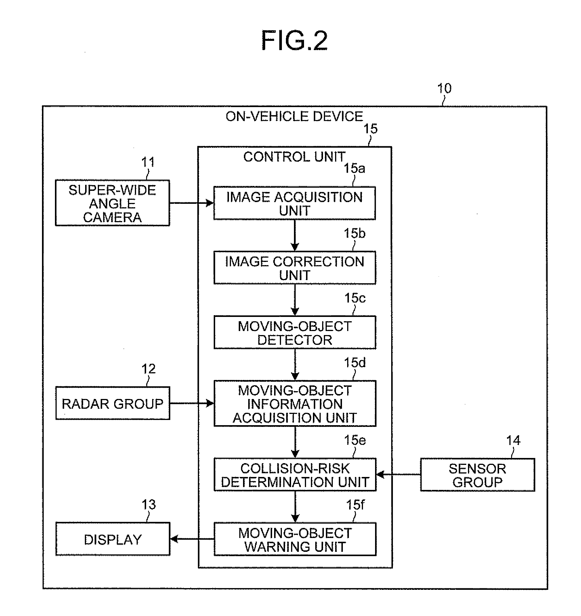
[0025]Preferred embodiments of the on-vehicle device and the recognition support system according to the present invention will be explained in detail below with reference to the accompanying drawings. Hereinafter, an overview of the on-vehicle device and the recognition support system according to the present invention will be explained with reference to FIGS. 1A and 1B, and then the embodiments of the on-vehicle device and the recognition support system according to the present invention will be explained with reference to FIG. 2 to FIG. 8B.

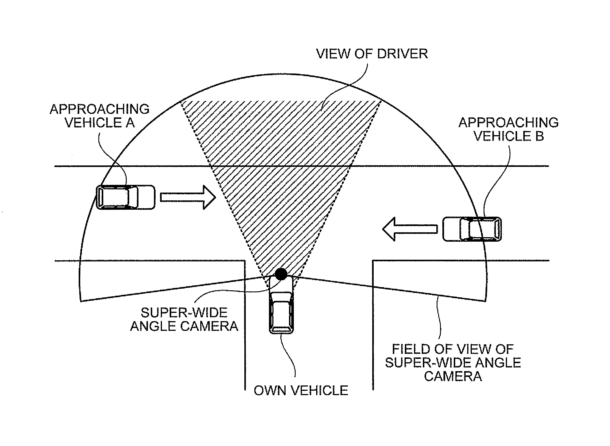
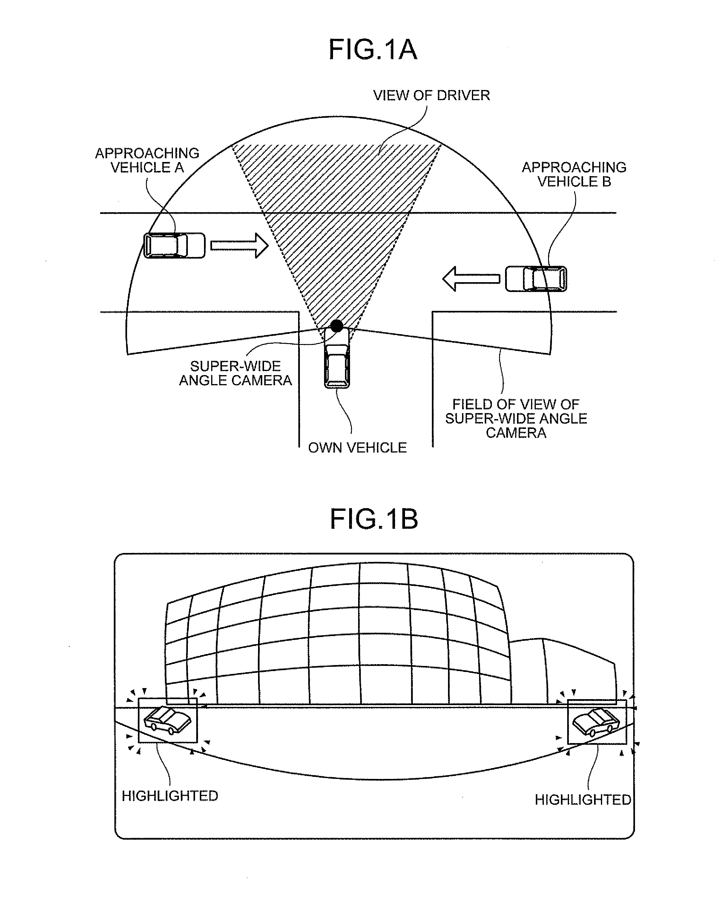
[0026]First, the overview of the on-vehicle device and the recognition support system according to the present invention will be explained with reference to FIGS. 1A and 1B. FIGS. 1A and 1B are diagrams illustrating the overview of the on-vehicle device and the recognition support system according to the present invention.

[0027]As shown in FIGS. 1A and 1B, the on-vehicle device and the recognition support system according to the present inventi...


PUM


Abstract

An on-vehicle device mounted on a vehicle includes an imaging unit that captures an image of a wide angle range through a curved light receiver, a moving-object detector that detects a moving object approaching an own vehicle from a mounting direction of the imaging unit and from any direction other than the mounting direction, based on the image captured by the imaging unit, a collision-risk determination unit that determines a degree of collision risk indicating a possibility of collision between the moving object detected by the moving-object detector and the own vehicle, and a moving-object warning unit that warns presence of the moving object included in an image portion in which a distortion of the image is a predetermined value or more, and warns the presence of the moving object according to the degree of collision risk determined by the collision-risk determination unit.

Description

CROSS-REFERENCE TO RELATED APPLICATION[0001]This application is based upon and claims the benefit of priority of the prior Japanese Patent Application No. 2009-272859, filed on Nov. 30, 2009, the entire contents of which are incorporated herein by reference.BACKGROUND OF THE INVENTION[0002]1. Field of the Invention[0003]The present invention relates to an on-vehicle device mounted on a vehicle and a recognition support system, and more particularly, to an on-vehicle device and a recognition support system capable of achieving cost reduction of the on-vehicle device and allowing a driver to reliably recognize the presence of a detected moving object while preventing detection omission of a moving object approaching an own vehicle from a blind corner for the driver.[0004]2. Description of the Related Art[0005]Recently, there have been developed a number of on-vehicle devices that detect a moving object around a vehicle by an image captured by a camera and by using sensors or the like ...

Claims


Application Information

Patent Timeline
Patent Type & Authority Applications(United States)
IPC IPC(8): B60Q1/00H04N7/18
CPCB60W30/0956B60W50/14G06K2209/23G08G1/164G06K9/00805G06T7/2066G06T2207/10016G06T2207/30261G08G1/166G08G1/167G06T7/269G06V20/58G06V2201/08
Inventor YAMAMOTO, TETSUOMURASHITA, KIMITAKASAWADA, YASUYOSHIKIRIYA, TAKECHIKA
Owner FUJITSU GENERAL LTD
Why Eureka
Try Eureka