Cutting insert and shim for heavy machining operations

a cutting insert and machining operation technology, applied in the direction of turning machine accessories, shaping cutters, manufacturing tools, etc., can solve the problems of cutting inserts securely, affecting the accuracy of planned cuts, and pressure loads suddenly to be removed from inserts, etc., to achieve the effect of heavy machining operations

Active Publication Date: 2011-06-02
KENNAMETAL INC
View PDF13 Cites 41 Cited by
  • Summary
  • Abstract
  • Description
  • Claims
  • Application Information

AI Technical Summary

Problems solved by technology

One problem encountered with conventional tool holders is that of holding the cutting insert securely in the pocket of the tool holder.
At the beginning of a cutting operation, the sudden transition from no load to extreme pressure load on the insert can cause the insert to shift position in the holder and thereby affect the accuracy of the planned cut.
At the end of the cutting operation, the sudden disengagement of the cutting insert from the workpiece causes the pressure load suddenly to be removed from the insert.
This sudden change in load can cause the insert to shift and distress any repeatable dimensional accuracy, which is essential for most tool holders, especially cutting inserts used in Numerically Controlled machines, to meet.
During the cutting operation, loads of up to 35,000 pounds may be encountered on the cutting insert which, if the insert is not precisely located and firmly held in the holder to begin with, can also cause shifting of the insert during the cutting operation.

Method used


Image

  • Cutting insert and shim for heavy machining operations
  • Cutting insert and shim for heavy machining operations
  • Cutting insert and shim for heavy machining operations

Examples


Embodiment Construction

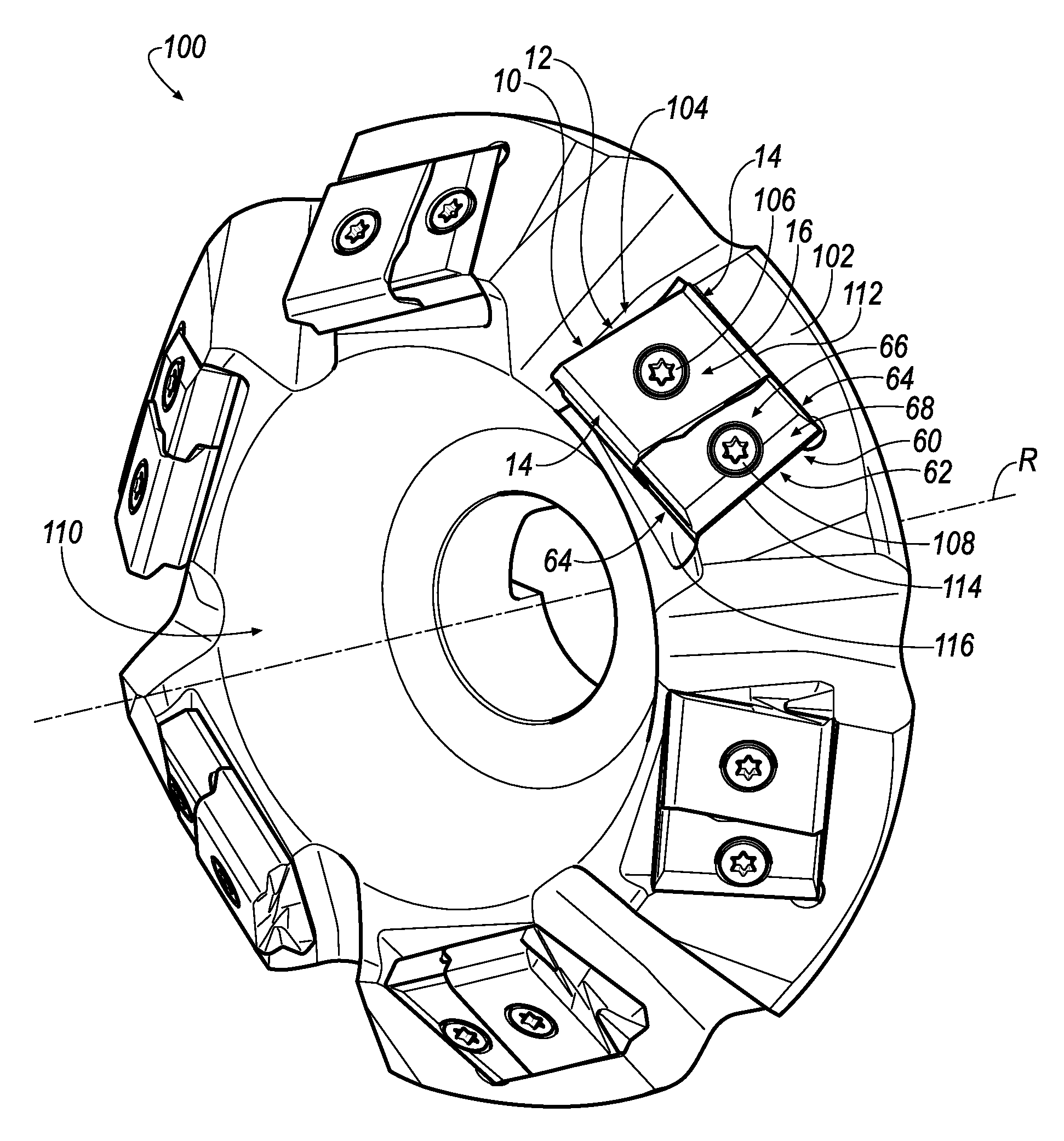
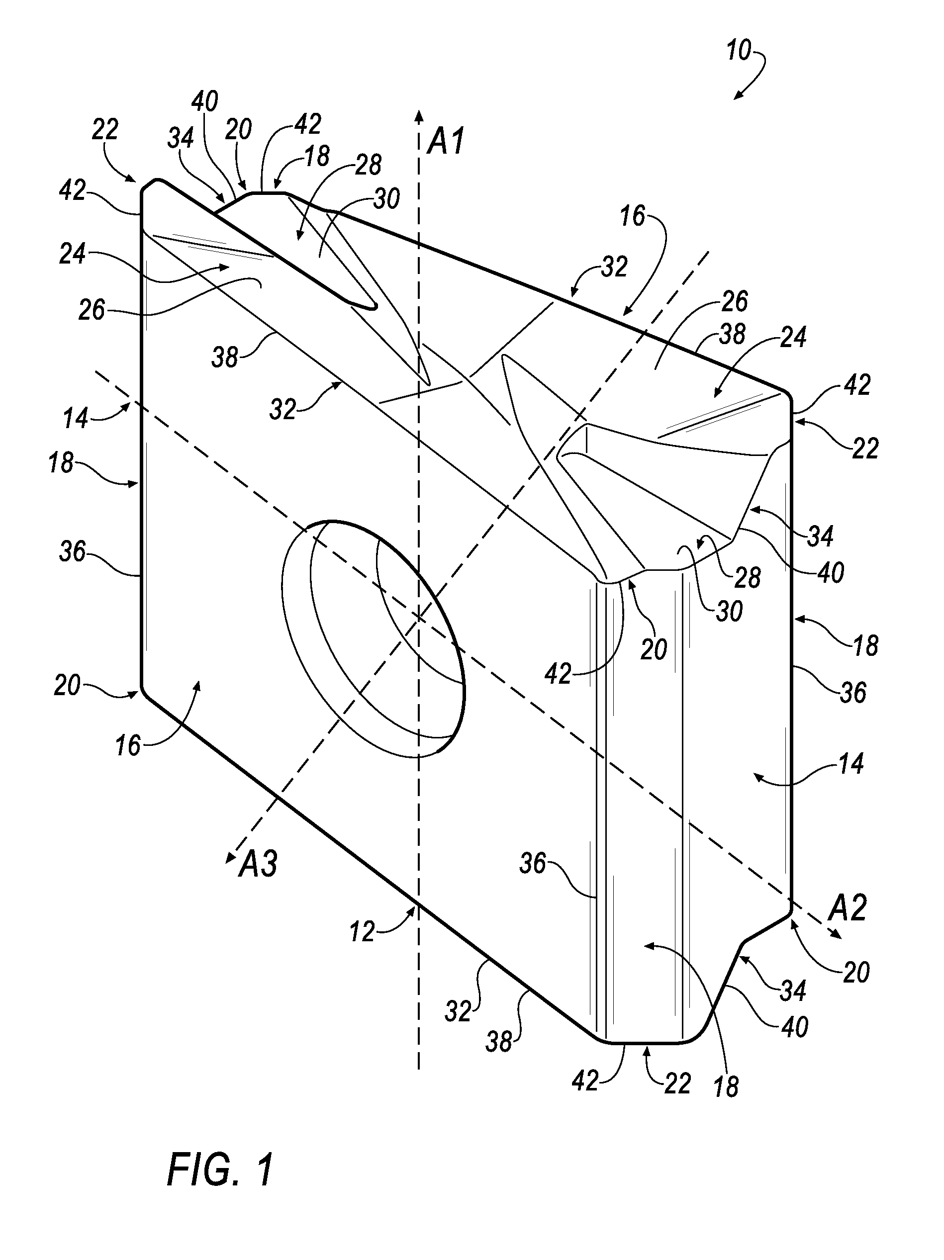
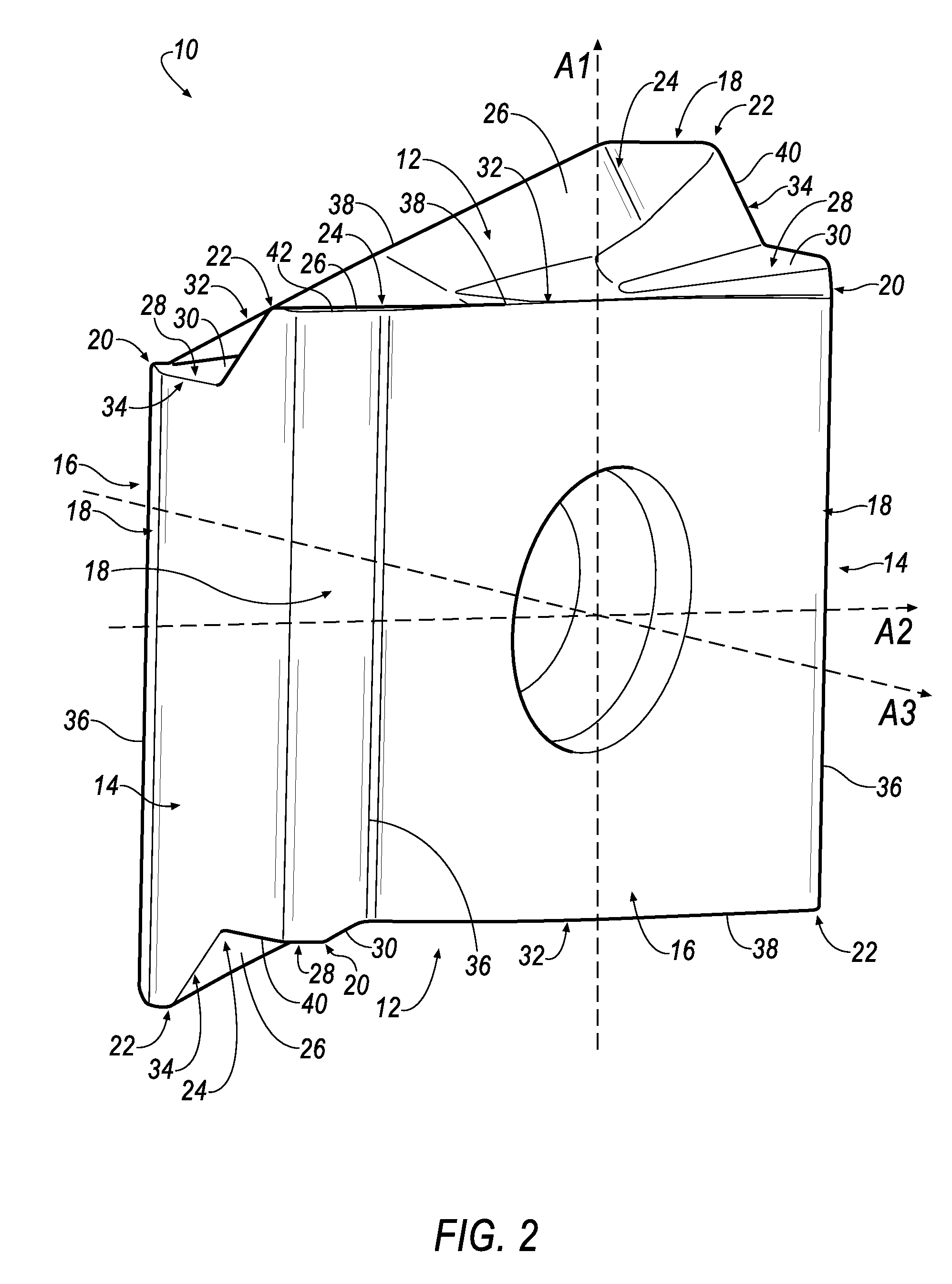
[0021]Referring now to FIGS. 1-5, a cutting insert 10 is shown according to an embodiment of the invention. In general, the cutting insert 10 is tangential and indexable. The cutting insert 10 is typically manufactured by form-pressing and sintering carbide powders using methods well-known in the art. The cutting insert 10 is generally rectangular in shape and has two identical opposing end surfaces 12, two identical opposing minor side surfaces 14 extending between the two opposing end surfaces 12, two identical opposing major side surfaces 16 extending between the end surfaces 12 and the minor side surfaces 14. Each end surface 12 has 180° rotational symmetry about a first central axis A1 passing through the two end surfaces 12, each minor side surface 14 has 180° rotational symmetry about a second central axis A2 passing through the two minor side surfaces 14, and each major side surface 16 has 180° rotational symmetry about a third central axis A3 passing through the two major s...


PUM

PropertyMeasurementUnit
lengthaaaaaaaaaa
cutting forcesaaaaaaaaaa
pressureaaaaaaaaaa

Abstract

A combination of a cutting insert and a shim. The cutting insert and shim have two opposing end surfaces with two identical opposing major side surfaces and two identical opposing minor side surfaces extending between the minor side surfaces. Each end surface of the insert has two lowered abutment members, each having a shim abutment surface for contacting the shim. One end surface of the shim has two raised abutment members, each having an insert abutment surface for contacting the insert. The abutment surfaces contact each other in an area where high cutting forces occur so as to help distribute the loads encountered in the cutting operation, as well as provide protection of the insert pocket in case of insert failure.

Description

FIELD OF THE INVENTION[0001]In general, the invention relates to a cutting insert and a cutting tool, and in particular to a combination of a cutting insert and shim for a milling cutter that contact with each other in an area where high cutting forces occur so as to help distribute the loads (stresses) encountered in the cutting operation, as well as provide protection of the insert pocket in case of insert failure.BACKGROUND OF THE INVENTION[0002]One problem encountered with conventional tool holders is that of holding the cutting insert securely in the pocket of the tool holder. At the beginning of a cutting operation, the sudden transition from no load to extreme pressure load on the insert can cause the insert to shift position in the holder and thereby affect the accuracy of the planned cut. At the end of the cutting operation, the sudden disengagement of the cutting insert from the workpiece causes the pressure load suddenly to be removed from the insert. This sudden change i...

Claims


Application Information

Patent Timeline
Patent Type & Authority Applications(United States)
IPC IPC(8): B23C5/22
CPCB23C5/06B23C5/2221B23C2200/085Y10T407/2274B23C2210/166Y10T407/23Y10T407/1924B23C2200/367B23C5/2213B23C5/20B23C5/22B23B27/16
Inventor KOVAC, JEFFREY FRANCISMYLAVARAM NIKHILESH, KUMAR REDDY
Owner KENNAMETAL INC
Why Eureka
Try Eureka