Electric pump

a technology of electric pump and rotor, which is applied in the direction of piston pump, positive displacement liquid engine, liquid fuel engine, etc., can solve the problems of motor output deterioration, large clearance between stator and rotor, and motor performance becoming unstabl

Inactive Publication Date: 2011-06-09
DENSO CORP
View PDF11 Cites 44 Cited by
  • Summary
  • Abstract
  • Description
  • Claims
  • Application Information

AI Technical Summary

Problems solved by technology

As a result, the inclination of the shaft causes unwanted deflection of the rotor in the radial direction, and thereby the performance of the motor becomes unstable.
Also, because the inclination of the shaft is relatively large, the

Method used


Image

  • Electric pump
  • Electric pump
  • Electric pump

Examples


Embodiment Construction

[0016]Electric pumps of embodiments of the present invention will be described with accompanying drawings.

One Embodiment

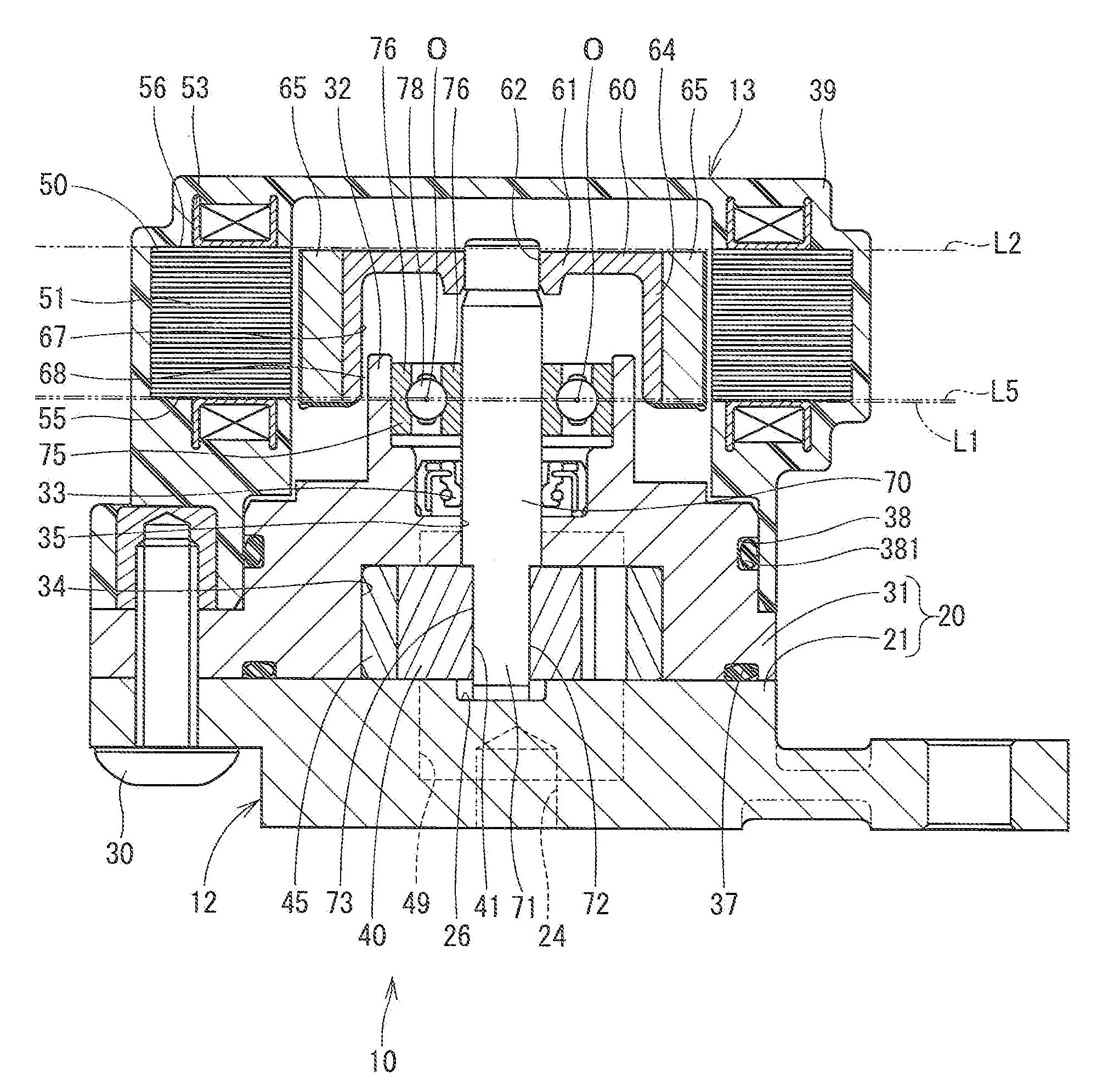
[0017]The electric pump of one embodiment of the present invention is applied to an oil pump that supplies hydraulic oil to an automatic transmission apparatus.

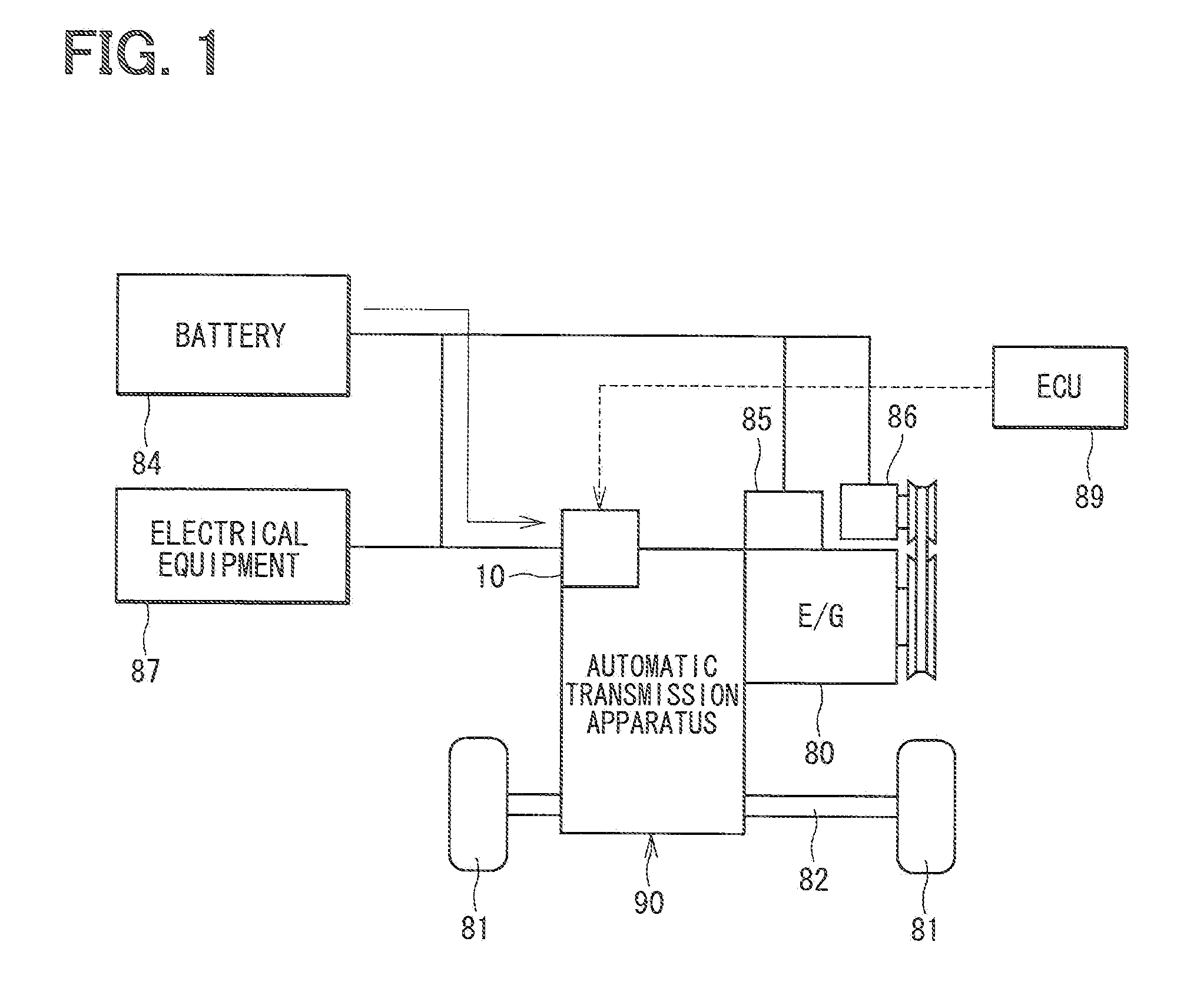
[0018]FIG. 1 illustrates a general configuration of a system according to the present embodiment.

[0019]An internal combustion engine 80 (hereinafter, referred to as “engine”) serves as a drive force generator for a vehicle, and has a crankshaft (not shown) that is mechanically connected with a drive shaft 82 connected with right and left drive wheels 81. An automatic transmission apparatus 90 is provided to a drive force transmission system that transmits drive force from the crankshaft to the drive wheels 81. The automatic transmission apparatus 90 is provided with an electric pump 10 that is driven based on electric power supplied from a battery 84.

[0020]The battery 84 is connected to the electric pump 10,...


PUM


Abstract

An electric pump includes a stator, a rotor, a shaft, a bearing part, and a pump unit. The stator has a magnetic part, and the stator forms a rotation magnetic field when a coil of the stator is energized. The bearing part has a longitudinal central position that is positioned on an imaginary plane perpendicular to a rotation axis of the rotor. The imaginary plane is positioned within an inner range defined between longitudinal end portions of the magnetic part of the stator.

Description

CROSS REFERENCE TO RELATED APPLICATION[0001]This application is based on and incorporates herein by reference Japanese Patent Application No. 2009-275569 filed on Dec. 3, 2009.BACKGROUND OF THE INVENTION[0002]1. Field of the Invention[0003]The present invention relates to an electric pump.[0004]2. Description of Related Art[0005]A conventional electric motor is known to rotate a shaft, which is rotatably supported by a bearing part, based on a magnetic field generated upon energization to a coil. For example, in an electric oil pump of JP-A-2003-269345, a bearing part of a motor is provided on a housing of the oil pump. Also, in JP-A-2005-160285, bearing parts are provided to both longitudinal ends of a rotor.[0006]The shaft of the electric motor in JP-A-2003-269345 is supported at one position. Also, the bearing part is displaced from the rotor and the stator in the longitudinal direction. As a result, the inclination of the shaft causes unwanted deflection of the rotor in the radi...

Claims


Application Information

Patent Timeline
IPC IPC(8): F04B35/04
CPCF01C21/02F01C21/104F04C2/102F04C11/008H02K7/14F04C2240/51F04C2240/601H02K7/085F04C2240/40
Inventor OISHI, KENICHIKURODA, TOMONOBUITOH, TAKU
Owner DENSO CORP
Why Eureka
Try Eureka