Vibrating compressible dental plate for correcting malocclusion

Inactive Publication Date: 2011-06-09
ADVANCED ORTHODONTICS & EDUCATION ASSOC LLC
View PDF93 Cites 54 Cited by
  • Summary
  • Abstract
  • Description
  • Claims
  • Application Information

AI Technical Summary

Benefits of technology

[0040]In addition to direct purchase of a complete system, leasing, rental, per procedure or other shared usage can reduce patient cost and allow recycling of system components. Specifically, the system provides methods for recycling the vibratory source, batteries, plugs, wires, and extraoral components, as well as motorized and/or computerized parts.
[0041]The system supports a business model that allows for a non-disposable component of the orthodontic treatment to be variable and proportional in cost to the duration of the treatment. The bite plate, in contrast, can be disposable or non-disposable. The device can be leased, rented, or purchased on a procedure basis to the patient directly or through the orthodontist or by a third party. The prop

Problems solved by technology

However, the usable force range is more limited, as patients cannot tolerate high forces.
Some patients may have

Method used


Image

  • Vibrating compressible dental plate for correcting malocclusion
  • Vibrating compressible dental plate for correcting malocclusion
  • Vibrating compressible dental plate for correcting malocclusion

Examples


example 1

Vibrational Orthodontic Device

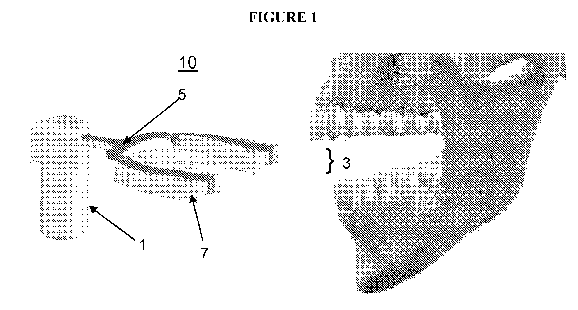
[0052]FIG. 1 shows one embodiment of an orthodontic treatment device 10. The device 10 has an intraoral bite plate 3 that is inserted into a patient's mouth. The bite plate 3 is connected to an extraoral vibration source 1 and interfaces with the dentition. The device 10 is clamped down by the patient's jaw on the bite plate 3 to secure it between the dental arches in the patient's mouth. The vibration source 1 in this embodiment is activated by pushing a button (not shown) mounted on the extraoral apparatus. The vibration source can alternatively be activated by sensing the patient bite pressure as stimuli with a microprocessor or some other mechanism translating the external stimuli into device function, including moisture or temperature sensing as well as salivary mineral content sensing.

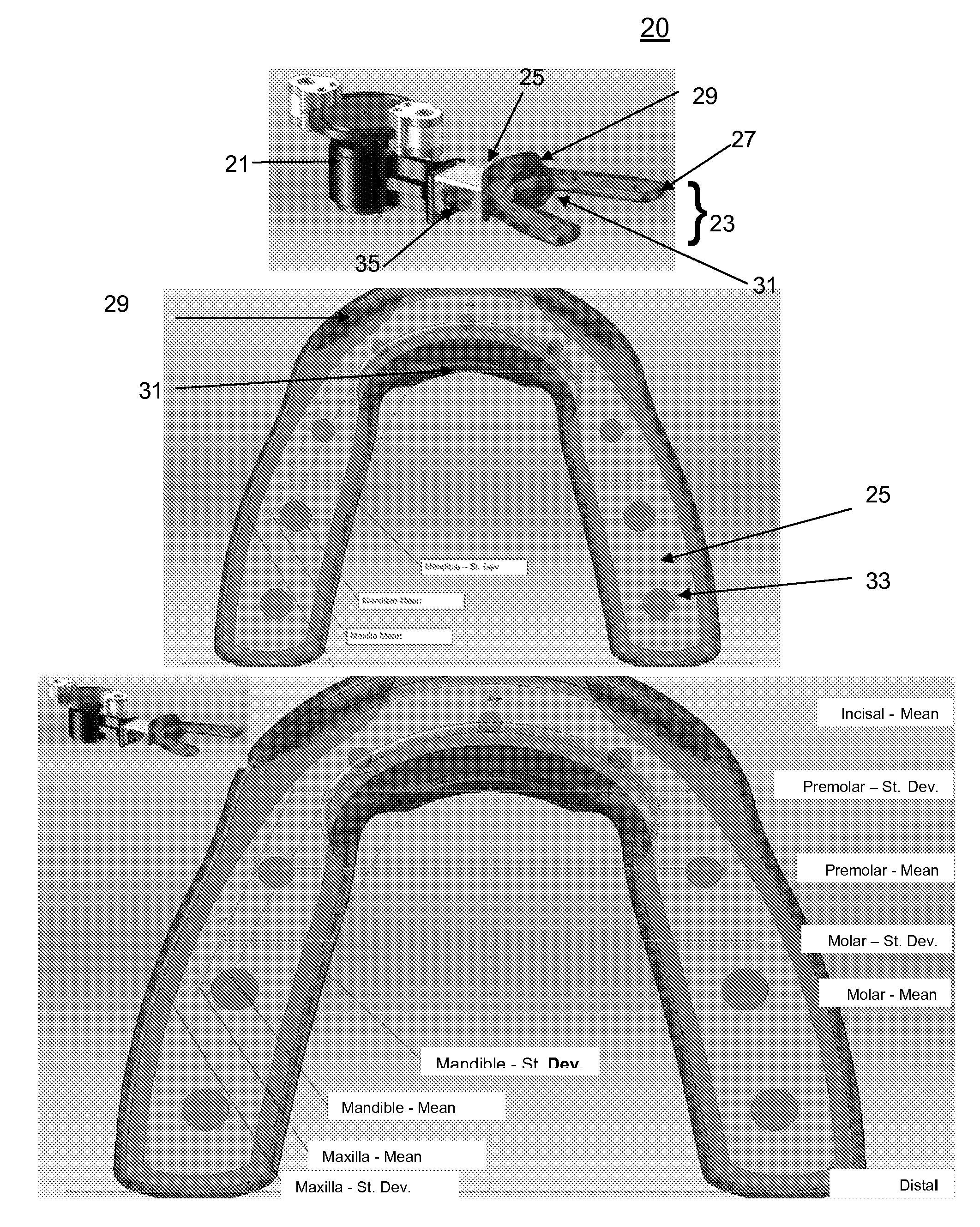
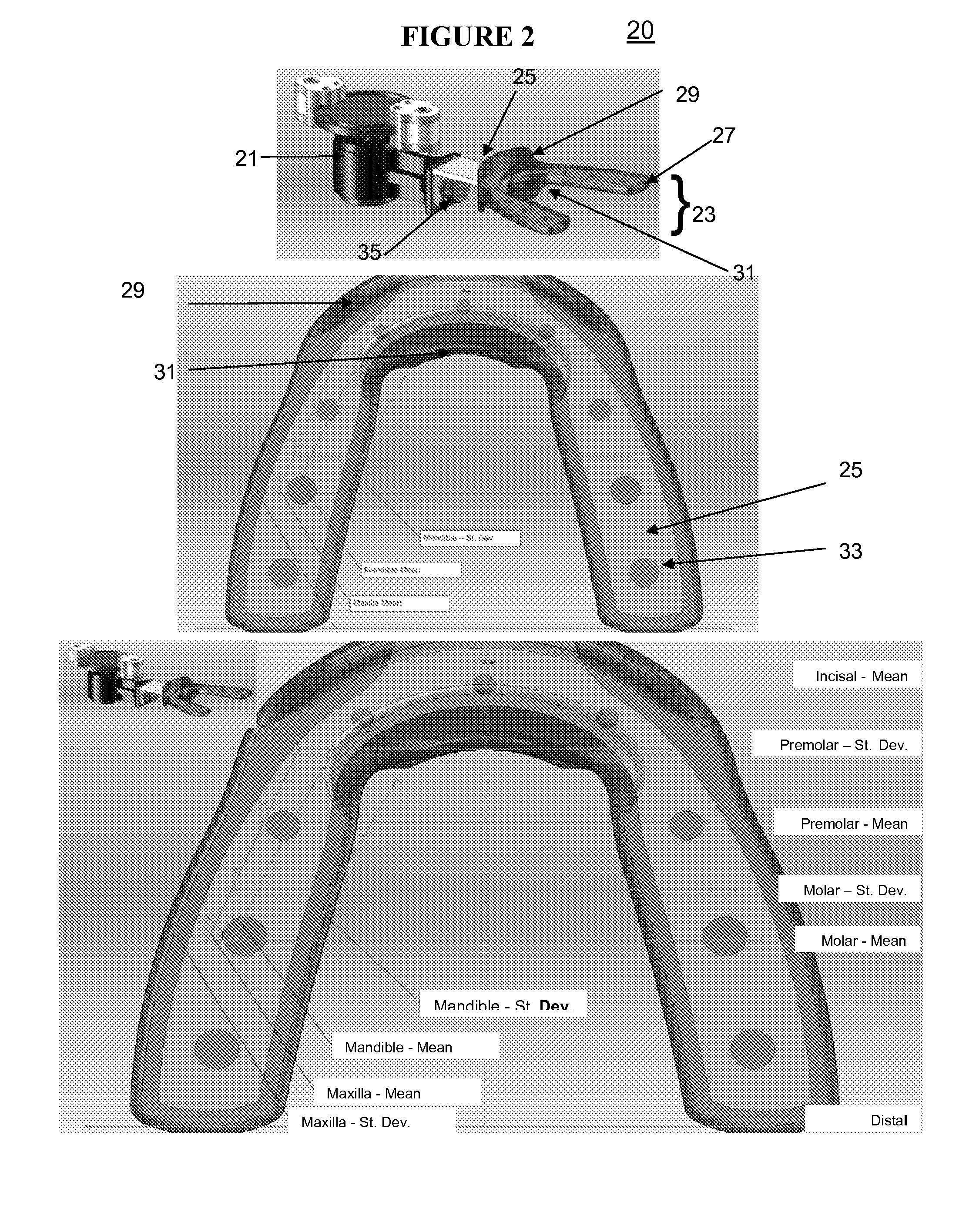
[0053]FIG. 2 shows another embodiment of an orthodontic treatment device 20. The bite plate 23 is connected to an extraoral programmable vibration source 21 and int...

example 2

Collapsible Bite Plates

[0068]When the bite plate is configured to allow significant masticating motions of the jaw, additional accelerative forces are brought into play, thus improving the speed of remodeling. In its simplest embodiment, the bite plate 41 has an upper surface 48 and lower surface 49, separated by a space 43. The space 43 is compressed with the masticating motion of the jaw, but returns to its original position when the pressure is removed. The resilience may be a consequence of material memory or the inclusion of an elastomeric filler inside the space, such as a gel, foam or polymer filler. Alternatively, the space may be mechanically restored, such as with the use of springs or hinges 44, 44, 45 or internal coils 47 that bias the space towards separation.

[0069]The vibrational orthodontic device may also be hinged to facilitate insertion and apply directional mechanical force. In one embodiment a semicircular or U-shaped orthodontic device is hinged 51 along the dis...


PUM


Abstract

A improved vibrating dental plate that allows accelerative forces in addition to vibrating forces to assist in remodeling is provided.

Description

PRIOR RELATED APPLICATIONS[0001]This application claims priority to 61 / 040,777, filed Mar. 31, 2008 and incorporated herein by reference.FEDERALLY SPONSORED RESEARCH STATEMENT[0002]Not applicable.REFERENCE TO MICROFICHE APPENDIX[0003]Not applicable.FIELD OF THE INVENTION[0004]The invention relates to systems and methods for correcting malocclusion.BACKGROUND OF THE INVENTION[0005]Orthodontics is a dental specialty that treats malocclusion through the displacement of teeth, as well as control and modification of facial growth. This process is usually accomplished using continuous mechanical force to induce bone remodeling, thereby enabling the teeth to move to a better position. In this approach, orthodontic braces, consisting of an archwire that applies a continuous static force to the teeth interfaces with brackets that are affixed to each tooth. As the teeth slowly move under the pressure, the arch wires are tightened to again apply pressure. Although effective, this widely accept...

Claims


Application Information

Patent Timeline
IPC IPC(8): A61C7/00
CPCA61C7/08A61C7/008
Inventor RUBIN, CLINTON T.TARVER, W. BRENTLOWE, MICHAEL K.
Owner ADVANCED ORTHODONTICS & EDUCATION ASSOC LLC
Why Eureka
Try Eureka