Fiber composite and process of manufacture

a fiber composite and fiber technology, applied in the field of graphite resin composite components, can solve the problems of significant quality control and production problems, difficult control of internal divisions, bridges or lumens placed in these tubes, and hardening of the material of the layup of the tennis racket, etc., and achieves the effect of increasing the injury of shoulders and elbows

Inactive Publication Date: 2011-06-09
XENE CORP
View PDF16 Cites 27 Cited by
  • Summary
  • Abstract
  • Description
  • Claims
  • Application Information

AI Technical Summary

Benefits of technology

[0012]Quite apart from the strength of the material of which the tennis racquet is made, in accordance with the invention it is also believed that the hollow nature of present state-of-the-art graphite racquets, in comparison to earlier generation solid wooden racquets, have increased injury to shoulders and elbows due to vibration and shock, particularly from off-center shots. This is because the hollow frame and open ended shaft at the handle is coupled, during play, to the hand and then to the arm.
[0013]In accordance with the invention, the opening for air injection at the bottom of the shaft is believed to worsen the shock that resonates at the handle of the racquet and propagates to and through the hand, arm and shoulder of the player.
[0014]Years of industry development have been invested to address the minimization of these propagated vibrations and shock, by implementing various methods of dampening the transmission of vibration from the handle of the racquet to the hand of the player.

Problems solved by technology

The result in the finished racquet is a hardening of the material of the layup.
While it may be possible, in principle to the form a multiple-tube composite structure, it has been found that any internal divisions, bridges or lumens placed in these tubes are difficult to control in their placement because of variations in bladder air pressure and layup characteristics along the length of the layup.
Attempts to include them in the past have been found to cause significant quality control and production problems.

Method used


Image

  • Fiber composite and process of manufacture
  • Fiber composite and process of manufacture
  • Fiber composite and process of manufacture

Examples


second embodiment

[0135]FIGS. 10 and 11 show a second embodiment, where fiber tubes are placed within microencapsulated filled tubes and heated to solidify the multiple tubes for additional strength and rigidity in the racquet.

[0136]It is noted that the formation of two tubes, the filling of the tubes 12 and 12′ with foam plastic and microencapsulated foaming agent and the wrapping of the two tubes with a third tube 16 may be done prior to the application of heat to cause the plastic to foam.

[0137]Alternatively, microencapsulated foam material may be included in two different forms to form the foam plastic. The individual tubes being formed as described above (optionally over first and second tubular sleeves), the resultant handle of the tennis racquet is wrapped with a second layer 16 of thermoplastic carbon fiber sheeting as described above (optionally over a third tubular sleeve), and then the assembly heated a second time to a lower temperature. At the high temperature of the first racquet format...

third embodiment

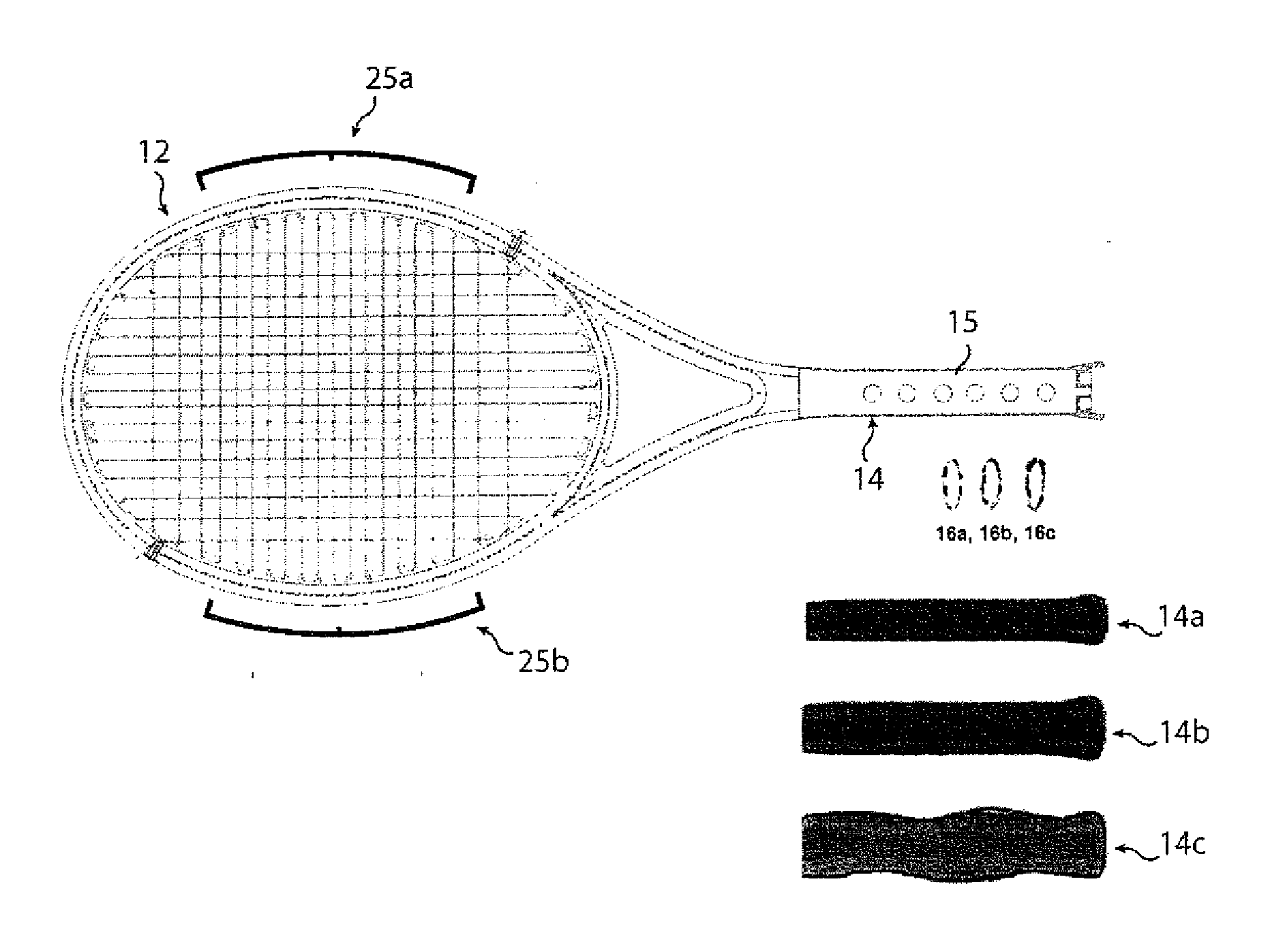
[0153]The necessity of weights and balances in racquets are well known in the industry. Conventionally, however, these weights could only be added after the solidification of the graphite fiber composite. The third embodiment allows weights to be added in the racquet head itself during the manufacturing process, for example by placement within sleeve 40 (FIG. 6), or placement within the mold cavity. Alternatively, during the manufacturing process, be incorporated for the receipt of weights. The advantage of doing this during the manufacturing process is the consistency and ease with which structural weight can be added during mass machine production to, for example, balance the racquet head, and the ease with which the same may be customized after production.

[0154]This embodiment also allows the formation of multiple structures impossible with conventional technology because air would not be able to pass through objects within the tube.

[0155]FIG. 17 shows a finished customizable rac...


PUM

PropertyMeasurementUnit
pressureaaaaaaaaaa
widthaaaaaaaaaa
temperatureaaaaaaaaaa

Abstract

The inventive fiber manufacturing process is particularly adapted for demanding applications such as sports racquets, including tennis racquets, badminton racquets and other sports applications. Because of the improved strength to weight ratio of components formed using the inventive method, a wide range of flexibility is achieved, allowing use of the inventive process to manufacture, for example, a fiber reinforced (for example, graphite) modular sports racquet, optionally provided with user-selectable weights and / or handle replacements. From the standpoint of the player, this allows a racquet frame featuring self customization. From the standpoint of a retailer, the benefit provided is reduction of inventory. The inventive fiber, for example graphite fiber) racquet frame is filled with a plastic foam and is formed using, for example, microencapsulation technology to time, generate and apply the pressure used to form the graphite composite material of which the racquet is comprised. Advantageously, inner and outer tubular members may be used to form the racquet frame, with the inner tubular member extending around the head of the racquet frame. This compares to the standard industry technique of air injection. The racquet is thus not hollow like conventional graphite racquets, and the walls therefore can be made thinner than those of existing graphite racquets still being of the same strength or being stronger, which gives the racquet exceptional performance. In addition, the overall dimensions of, for example the cross-section, of the racquet can also be reduced while still maintaining performance characteristics.

Description

CROSS REFERENCE TO RELATED APPLICATIONS[0001]This application is a continuation-in-part of PCT application No. PCT / 2010 / 038664, which in turn claims priority of Chinese patent application number 200910040320.9, filed on Jun. 18, 2009 in the People's Republic of China, and the priority of U.S. Provisional Patent Application No. 61-285,051, filed on Dec. 9, 2009, the disclosures of which are incorporated herein by reference.TECHNICAL FIELD[0002]The invention relates to apparatus and methods for graphite resin composite members, such as sports racquet frames, golf club shafts and bicycle frames.STATEMENT REGARDING FEDERALLY SPONSORED RESEARCH OR DEVELOPMENT [0003](Not applicable)BACKGROUND OF THE INVENTION[0004]For many years, graphite composite sports racquet frames have been produced by manual labor in molds using air injection. In a typical process, a “layup” is created by manually rolling multiple sheets or laminations (which take the form of strips of planar material), commonly f...

Claims


Application Information

Patent Timeline
Patent Type & Authority Applications(United States)
IPC IPC(8): A63B49/10
CPCA63B49/0276Y10T156/103A63B49/04A63B49/10A63B59/0014A63B59/0074A63B59/0092A63B2209/02A63B2209/023B29C44/16B29C70/446B29L2031/5245B32B2307/544B32B2307/558B32B2309/12B29C70/68A63B49/0288A63B49/035A63B60/10A63B49/032A63B60/02A63B60/06A63B60/54A63B60/08A63B60/42A63B49/11A63B60/00
Inventor HSU, CHIEN SHENGCHOE, JERRY
Owner XENE CORP
Why Eureka
Try Eureka