Recording medium supply device and recording apparatus

Inactive Publication Date: 2011-06-16
CANON KK
View PDF17 Cites 3 Cited by
  • Summary
  • Abstract
  • Description
  • Claims
  • Application Information

AI Technical Summary

Benefits of technology

[0007]The object of the invention is to provide a recording medium supply device capable of suppressing a recording medium projecting out of a cassette in a case where the position of the lead

Problems solved by technology

In the recording apparatuses in which recording media are stacked on the cassette which is attachable to and detachable from the main body of the apparatus as described above, if a recording medium d

Method used


Image

  • Recording medium supply device and recording apparatus
  • Recording medium supply device and recording apparatus
  • Recording medium supply device and recording apparatus

Examples


first embodiment

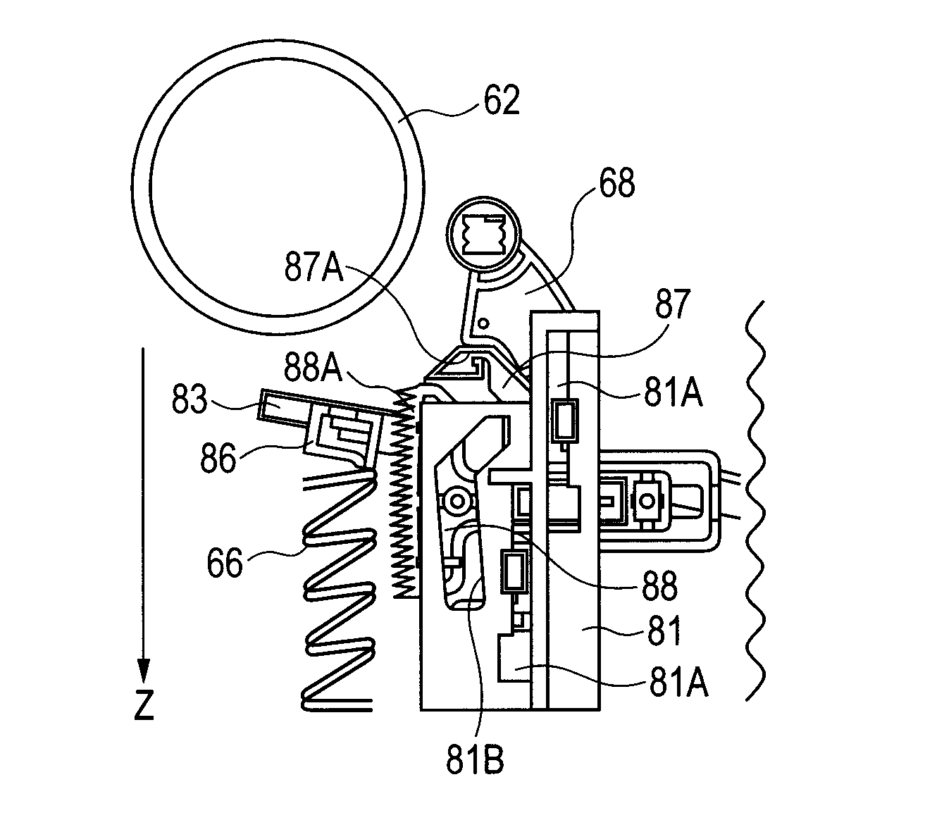
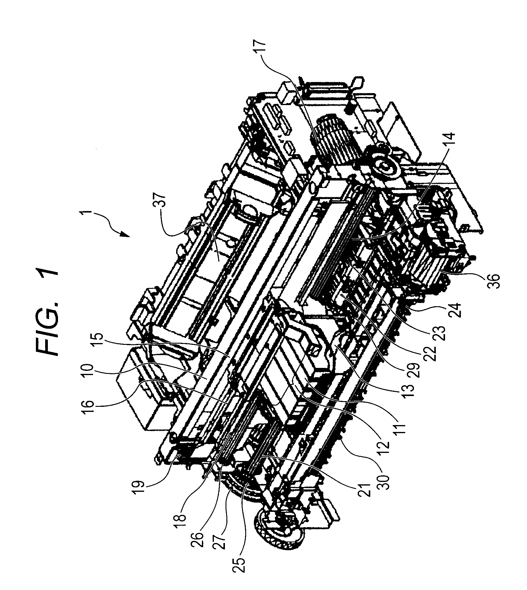
[0026]FIG. 1 is a perspective view illustrating the construction of one embodiment of a main body which constitutes the recording apparatus of the invention.

[0027]As illustrated in FIG. 1, in the main body 1 of the recording apparatus of the present embodiment, a chassis 10 supports some of constituent elements of the main body 1. A recording head 11 supported by the chassis discharges ink to perform recording. The ink to be discharged by the recording head 11 is stored in an ink tank 12. The ink tank 12 is held by a carriage 13, and the carriage 13 scans in a direction (main scanning direction) which intersects a conveying direction (sub-scanning direction) of a sheet-like recording medium (recording paper in the present embodiment). The carriage 13 is supported by a guide rail 15 parallel to a guide shaft 14. Additionally, the carriage 13 is driven by a carriage belt 16, and the carriage belt 16 is driven by a carriage motor via a pulley. The position of the carriage 13 is detecte...

second embodiment

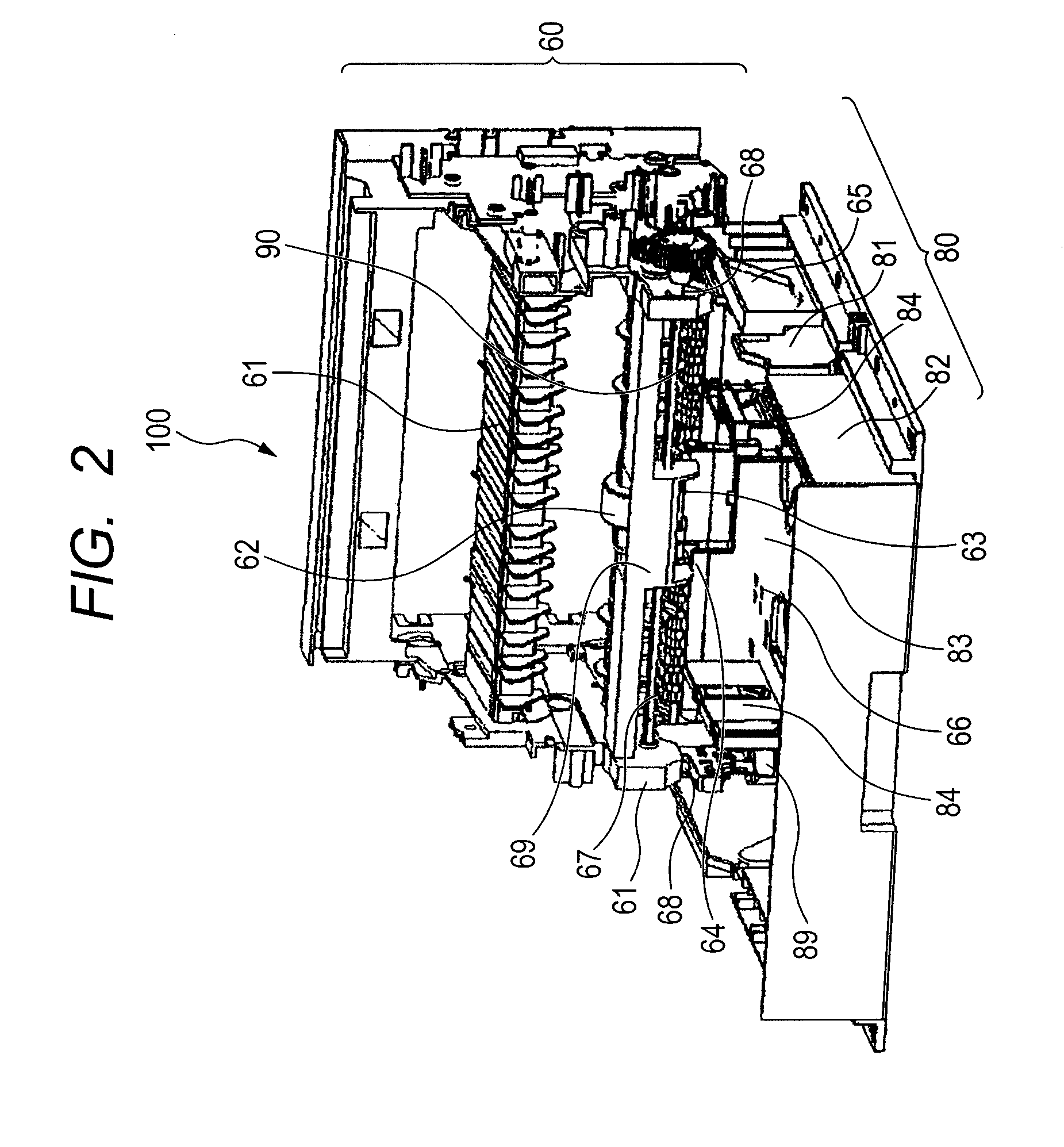
[0057]FIG. 7 is a perspective view illustrating chief parts of a recording medium supply device of the present embodiment. Additionally, FIGS. 8A to 8D are cross-sectional views illustrating a series of operations which is performed when the cassette is attached to and detached from the recording medium supply device of the present embodiment. In addition, description of the same construction as the construction described in the first embodiment will be omitted. Additionally, the recording medium supply device 200 of the present embodiment is attachable to the main body 1 similarly to the recording medium supply device 100 described in the first embodiment.

[0058]First, the operation of attaching the cassette 80 to the main body 1 will be described.

[0059]FIG. 8A illustrates the standby state of in which the attachment of the cassette 80 to the main body 1 stands by. In addition, in the present embodiment, as illustrated in FIG. 7, a projection preventing member 91 is rotatably attach...

third embodiment

[0069]FIG. 9 is a perspective view illustrating chief parts of a recording medium supply device of the present embodiment. Additionally, FIGS. 10A to 10C are cross-sectional views illustrating a series of operations which is performed when the cassette is attached and detached and when a recording medium is conveyed, in the recording medium supply device of the present embodiment. In addition, description of the same construction as the construction described in the first embodiment will be omitted. Additionally, the recording medium supply device 300 of the present embodiment is attachable to the main body 1 similarly to the recording medium supply device 100 described in the first embodiment.

[0070]First, the operation of attaching the cassette 80 to the main body 1 will be described.

[0071]FIG. 10A illustrates the standby state of in which the attachment of the cassette 80 to the main body 1 stands by. In addition, a spring 94 is attached to the lower end of the projection preventi...


PUM


Abstract

A recording medium supply device includes a cassette attachable to and detachable from a main body and capable of stacking recording medium thereon, a feeding roller which feeds the uppermost recording medium to the main body from a leading end of the recording medium, a regulating member which is arranged forward in the direction in which the cassette is removed from the main body as seen from the feeding roller, and a projection preventing member attached adjacent to the tip portion of the cassette facing the leading end of the recording medium. The position of the lower end of the regulating member is higher than the cassette attached to the main body, and lower than the lower end of the feeding roller, and the position of the upper end of the projection preventing member is higher than the position of the lower end of the regulating member.

Description

BACKGROUND OF THE INVENTION[0001]1. Field of the Invention[0002]The present invention relates to a recording medium supply device including a cassette attachable to and detachable from a main body of a recording apparatus and capable of stacking a recording medium thereon, and a recording apparatus.[0003]2. Description of the Related Art[0004]Conventionally, among recording apparatuses represented by a printer or the like, there are recording apparatuses in which recording media (for example, recording papers) are stacked on a cassette which is attachable to and detachable from the main body of the apparatus, and a recording medium on the uppermost layer is conveyed to the main body of the apparatus by a conveying roller arranged above the cassette.[0005]In the recording apparatuses in which recording media are stacked on the cassette which is attachable to and detachable from the main body of the apparatus as described above, if a recording medium during conveyance is left in the c...

Claims


Application Information

Patent Timeline
IPC IPC(8): B65H5/06
CPCB65H1/266B65H3/0607B65H2403/512B65H1/00B65H2601/2525B65H2801/06B65H2405/1117
Inventor TOKISAWA, TOSHIAKIHAMANO, TETSUKAWAZOE, KENJIMORINAGA, KAZUYUKISHIMMACHI, MASAYA
Owner CANON KK
Why Eureka
Try Eureka