Handlebar fixing structure

a technology for fixing structures and handlebars, which is applied in the direction of friction roller based transmission, steering devices, cycle equipments, etc., can solve the problems of less likely to be secured the rigidity of the fixing of the handlebars, and achieve the effect of high vibration absorption and high position

Inactive Publication Date: 2016-02-04
HONDA MOTOR CO LTD
View PDF24 Cites 3 Cited by
  • Summary
  • Abstract
  • Description
  • Claims
  • Application Information

AI Technical Summary

Benefits of technology

[0007]The present invention has been made in view of such a situation as described above. It is an object of an embodiment of the present invention to provide a handlebar fixing structure that allows a handlebar to be attached to a high position and has high vibration absorbency.

Problems solved by technology

However, if the handlebar post in the conventional structure is simply elongated upwardly, then the load by a bending moment or the like which acts on the elastic member increases as the length of the handlebar posts increases and the attachment rigidity of the handlebar becomes less likely to be secured.

Method used


Image

  • Handlebar fixing structure
  • Handlebar fixing structure
  • Handlebar fixing structure

Examples


Embodiment Construction

[0058]In the following, an embodiment of the present invention is described with reference to the drawings. It is to be noted that, unless otherwise specified, representations of directions such as forward, rearward, leftward, rightward, upward and downward directions are the same as the directions as viewed from a vehicle body. Further, reference characters FR, UP and LH depicted in the drawings indicate the forward direction, upward direction and leftward direction of the vehicle body, respectively.

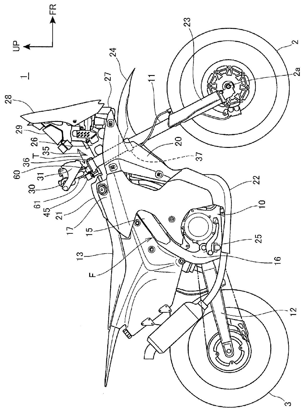
[0059]FIG. 1 is a right side elevational view of a motorcycle 1 according to an embodiment of the present invention. It is to be noted that, where left and right members are provided in a pair, only the right one of the members is depicted in FIG. 1.

[0060]The motorcycle 1 is a vehicle in which an engine 10 as a power unit is supported on a vehicle body frame F and a pair of left and right front forks 11 are steerably supported at a front end of the vehicle body frame F. A front wheel 2 ...


PUM


Abstract

A handlebar fixing structure enabling a handlebar to be attached to a high position to provide high vibration absorbency. The handlebar fixing structure includes a handlebar, a handlebar post supported above a steering system, and a handlebar clamper for fixing the handlebar to the handlebar post. The handlebar clamper includes a first damper member and a second damper member disposed so as to sandwich a cylindrical portion of the handlebar post and the handlebar from a direction orthogonal to the vehicle widthwise direction. An elastic member is interposed between the first clamper member and the handlebar post and between the second damper member and the handlebar post. The first damper member and the second clamper member are coupled with each other by a bolt and include abutting faces for abutting with each other so as to receive an axial force of the bolt.

Description

CROSS-REFERENCE TO RELATED APPLICATIONS[0001]The present application claims priority under 35 USC 119 to Japanese Patent Application No. 2014-156201 filed Jul. 31, 2014 and Japanese Patent Application No. 2014-187775 filed Sep. 16, 2014 the entire contents of which are hereby incorporated by reference.BACKGROUND OF THE INVENTION[0002]1. Field of the Invention[0003]The present invention relates to a handlebar fixing structure.[0004]2. Description of Background Art[0005]A handlebar fixing structure is known wherein a handlebar post for clamping a handlebar is fixed to a top bridge at an upper portion of a steering system. A handlebar fixing structure is known wherein the handlebar post is fixed through an elastic member in order to prevent transmission of driving vibration, engine vibration and so forth to the hands of the driver. See, for example, Japanese Patent Laid-Open No. 2012-144145. In the handlebar fixing structure for Japanese Patent Laid-Open No. 2012-144145, the elastic me...

Claims


Application Information

Patent Timeline
Patent Type & Authority Applications(United States)
IPC IPC(8): B62K21/20B62K21/08
CPCB62K21/08B62K21/20B62K11/14
Inventor TOMURA, KINEOMORI, YOTARO
Owner HONDA MOTOR CO LTD
Why Eureka
Try Eureka