System for determining the position of a vehicle, vehicle therewith, and method therefor

a vehicle position and vehicle technology, applied in the direction of vehicle position/course/altitude control, process and machine control, instruments, etc., can solve the problems of deteriorating accuracy, undersampling the magnetic field strength on the outer side of the bend, and not being able to accurately describe the detection of magnets

Active Publication Date: 2017-08-08
2 GETTHERE
View PDF19 Cites 2 Cited by
  • Summary
  • Abstract
  • Description
  • Claims
  • Application Information

AI Technical Summary

Benefits of technology

[0006]The object of the present invention is to provide a system for determining the position of a vehicle, wherein the deterioration of the accuracy when the vehicle negotiates a bend, is substantially less compared to the described prior art.

Problems solved by technology

The described detection of magnets is usually not sufficient to determine the position, as individual magnets can normally not be distinguished from each other.
A drawback of this known system is that when the vehicle negotiates a bend, the sensors at the outer side of the bend are undersampling the magnetic field strength, while the sensors at the inner side of the bend are oversampling the magnetic field strength.
Although the latter causes less problems with the processing power available to present day digital signal processors, the former causes a deterioration of the accuracy of the determined position when the vehicle negotiates a bend.

Method used


Image

  • System for determining the position of a vehicle, vehicle therewith, and method therefor
  • System for determining the position of a vehicle, vehicle therewith, and method therefor
  • System for determining the position of a vehicle, vehicle therewith, and method therefor

Examples


Embodiment Construction

[0021]Further embodiments and advantages thereof will be described below with reference to the accompanying drawings, wherein:

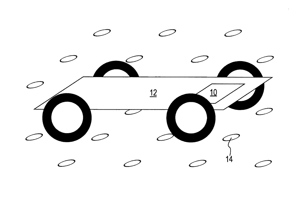
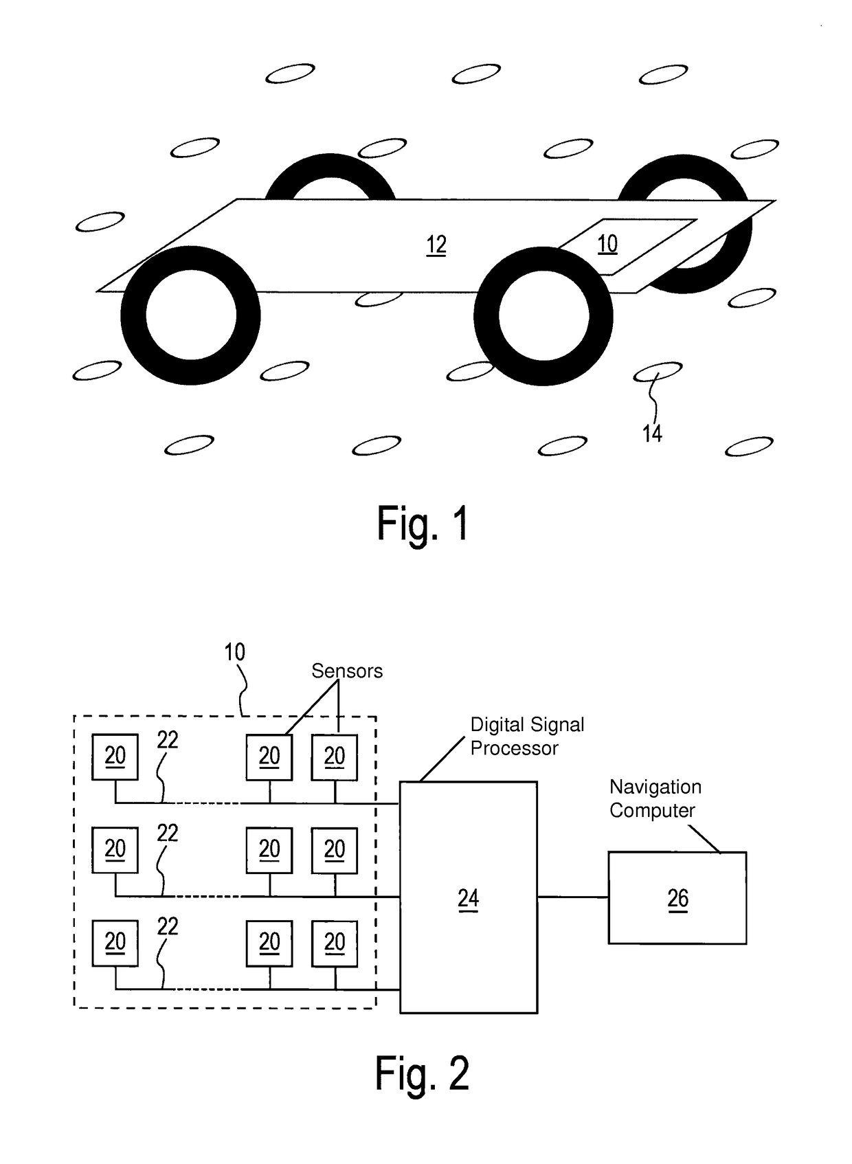
[0022]When a magnetic marker element 14 passes under a certain minimum number of sensors 20, the position of the vehicle 12 relative to the magnetic marker element 14 can be estimated. The minimum number of sensors required can be obtained by means of, for example, the Fisher Information Matrix. The magnetic field generated by the magnetic marker element 14 is sensed in one or more of the magnetic sensors 20. The magnetic sensors 20 are connected to a digital signal processor (DSP) 24. The DSP 24 fits the signals coming from the magnetic sensors 20 to a 3-dimensional model of the magnetic field of a magnetic marker element 14. From the fitted model, the position of the magnetic marker element 14 is obtained relative to the array 10 of magnetic sensors. Consequently, from a known position of a magnetic marker element 14, the position of the vehicle 12 is obtai...


PUM


Abstract

A system for determining the position of a vehicle includes a plurality of sensors for measuring the magnetic field strength of a magnet, means and is configured for determining the position of the magnet with respect to a plurality of sensors wherein the plurality of sensors are arranged in a two-dimensions array.

Description

FIELD OF THE INVENTION[0001]The present invention relates to a system for determining the position of a vehicle.[0002]The invention further relates to a vehicle comprising such a system.[0003]The invention also relates to a method for determining the position of a vehicle.BACKGROUND OF THE INVENTION[0004]Systems for determining the position of a vehicle are known for many years. One such known system makes use of a grid of magnets that is provided in the surface whereon the vehicle moves. The system comprises a plurality of sensors that are able to sense the strength of a magnetic field. The plurality of sensors is arranged in a lateral direction of the vehicle, in order to ensure that a magnet arranged in the ground surface is detected when the vehicle passes over the magnet. The signals from the sensors are periodically sampled and provided to computation means to calculate the position of the sensed magnet with respect to the sensors. The described detection of magnets is usually...

Claims


Application Information

Patent Timeline
Patent Type & Authority Patents(United States)
IPC IPC(8): G05D1/02
CPCG05D1/0261G05D1/02
Inventor SIEBERT, RALF
Owner 2 GETTHERE
Why Eureka
Try Eureka