Wall-mounted dispenser for liquids

a dispenser and wall mount technology, applied in the direction of liquid handling, instruments, closures using stoppers, etc., can solve the problems of difficult to see into the interior of the dispenser, the sight window is generally not low enough on the cover, and it is not really possible to obtain a good view, etc., to achieve the effect of more efficient shipping and handling of replacement cartridges

Inactive Publication Date: 2005-04-12
KANFER JOSEPH S
View PDF11 Cites 103 Cited by
  • Summary
  • Abstract
  • Description
  • Claims
  • Application Information

AI Technical Summary

Benefits of technology

It has been found that more efficient shipping and handling of replacement cartridges can be achieved by providing a dispenser having a pocket formed by a bag retainer and pump support with side and front walls attached to and projecting from the base or wall-mounting plate of the dispenser and which is capable of accommodating a collapsible bag of material without the need for providing a supporting box therearound. Such a bag retainer and pump support will also serve to protect the bag from pinching or puncture as the dispenser is opened and closed.

Problems solved by technology

The difficulty is that, in practice, it is not really possible to obtain a good view through these windows for several reasons.
One is that it is generally not possible to position the sight windows low enough down on the cover to accurately ascertain when the refill unit is nearly out of material because of the pumping mechanism usually employed.
Another is that the interior of the dispenser is unilluminated so that it is quite difficult to see into the interior of the dispenser.
Finally, as the bags empty, they tend to collapse and wrinkle so that the view of the contents is further impaired.
That is, the optimum would be for the window to rest against a relatively flat surface which is not possible once the bag begins to empty.
Inasmuch as many of these dispensers are located in public or commercial establishments and are refilled by maintenance people, it would save considerable time, and thus considerable expense, to provide a means whereby maintenance personnel can, at a glance, without opening the dispenser, ascertain whether refills are required.

Method used


Image

  • Wall-mounted dispenser for liquids
  • Wall-mounted dispenser for liquids
  • Wall-mounted dispenser for liquids

Examples


Embodiment Construction

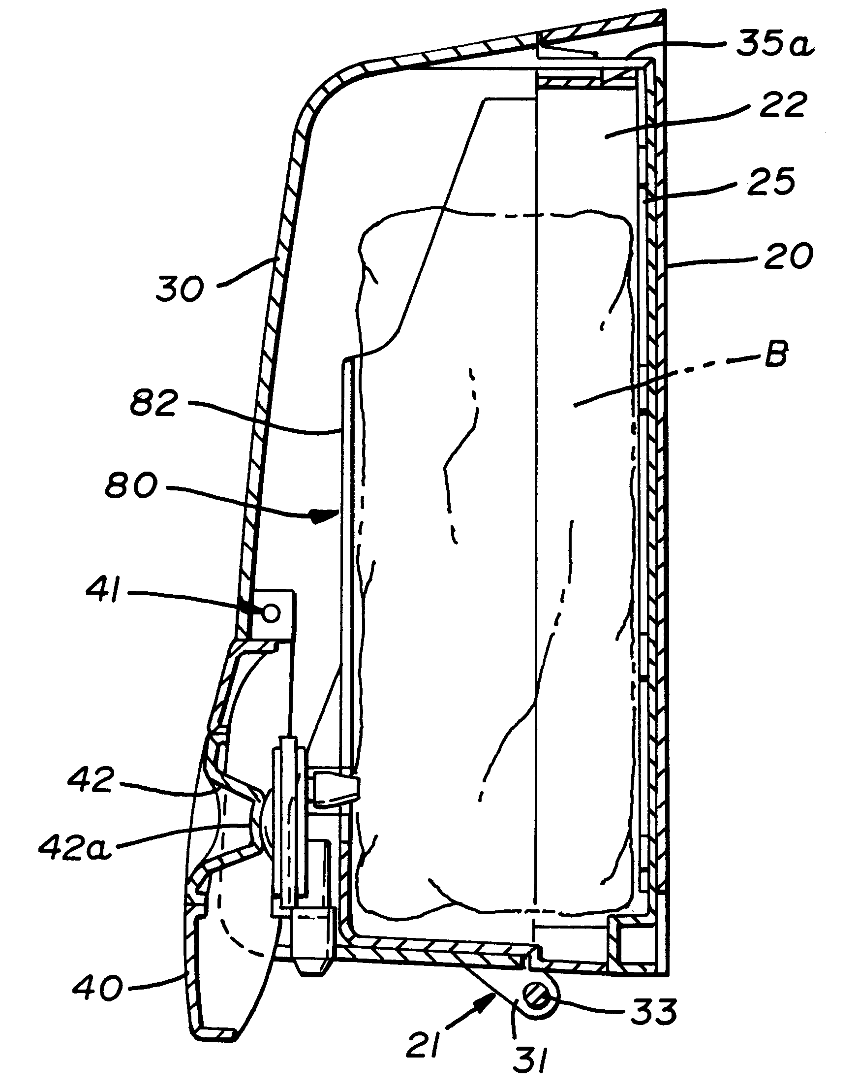
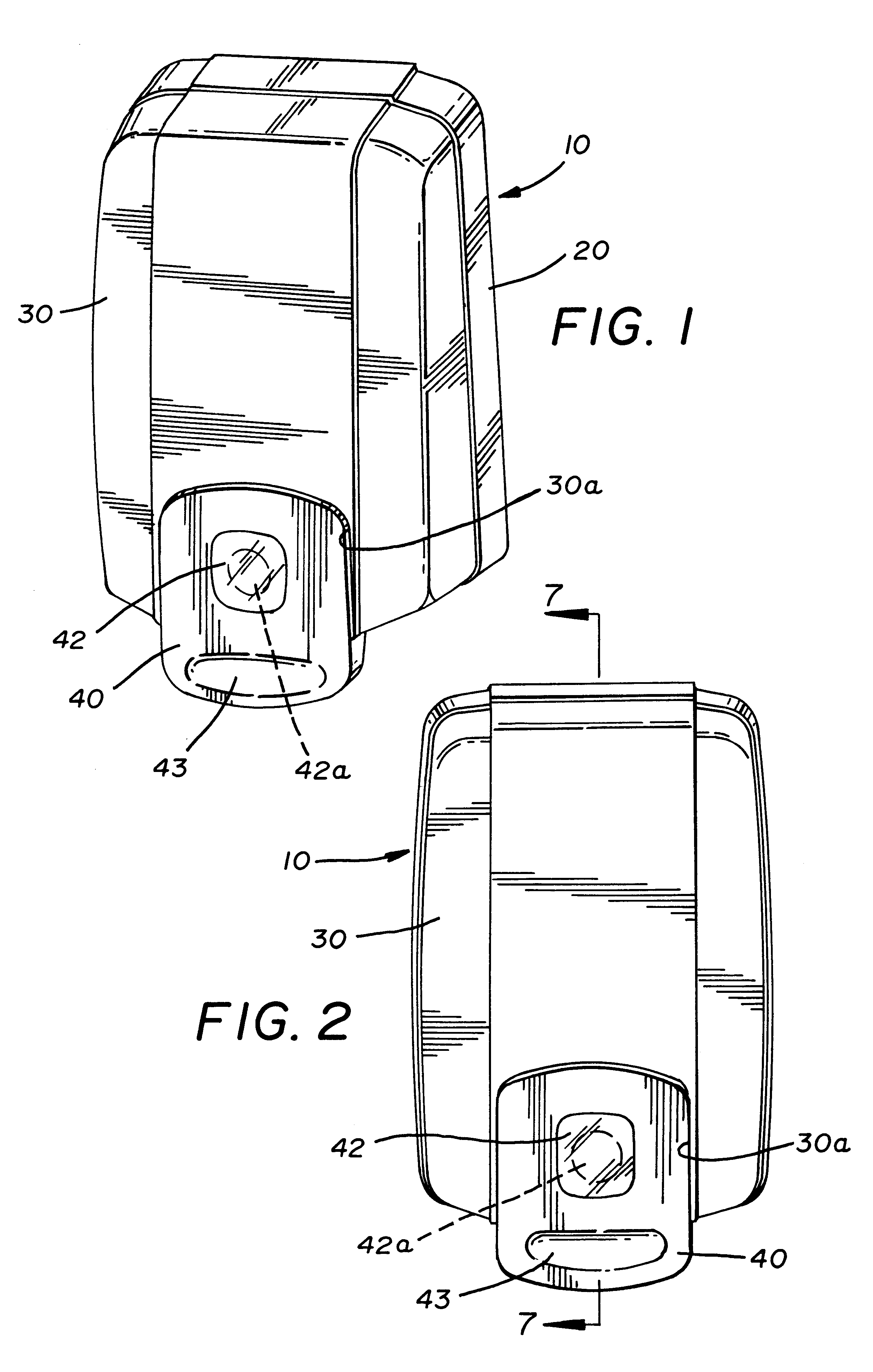
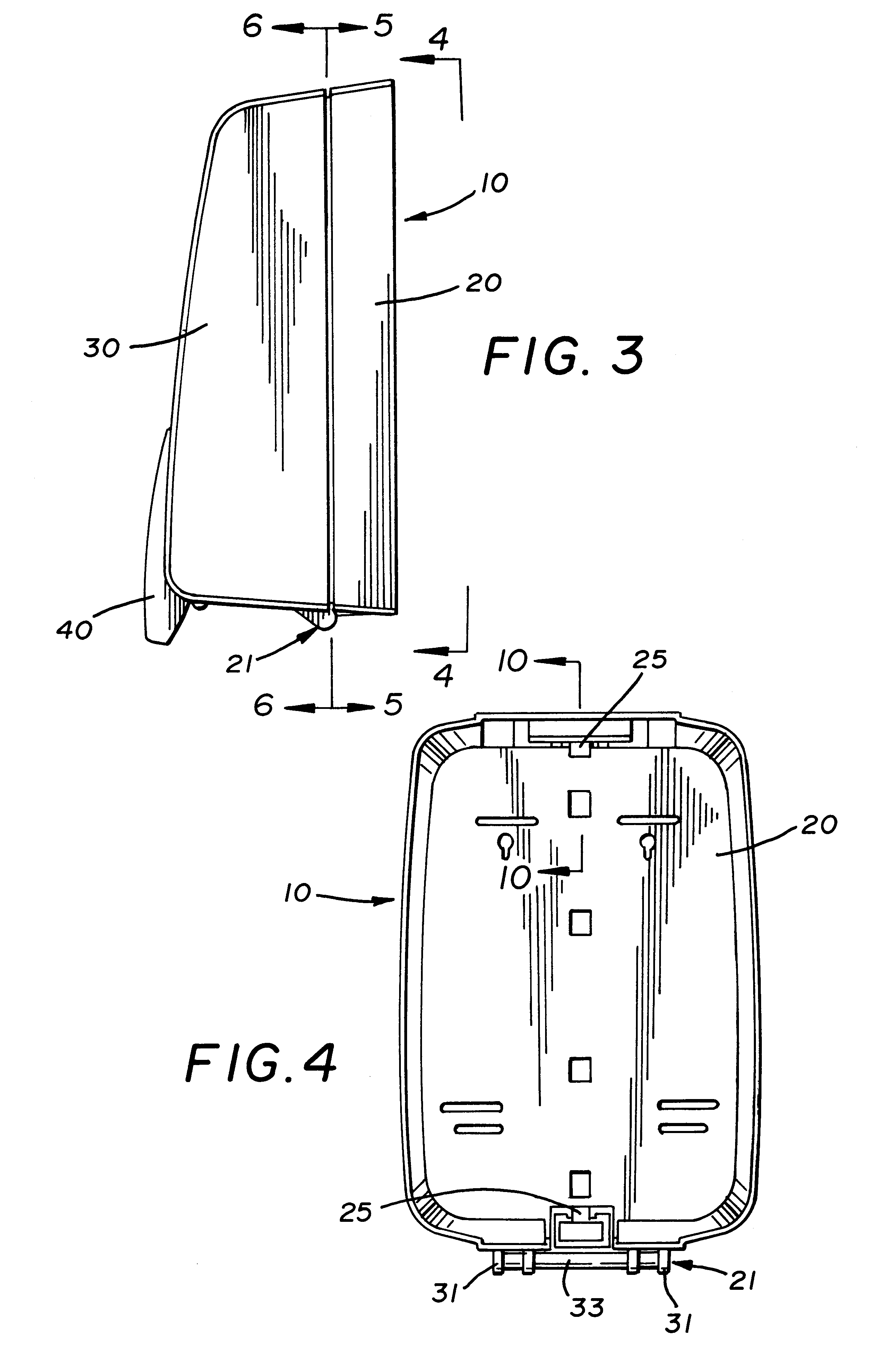
Referring then to FIGS. 1 through 4 of the drawings, it will be seen that the improved dispenser, generally indicated by the numeral 10, includes a back plate 20, a cover 30, and a pressure or push bar 40.

The cover 30 is hingedly connected to the back plate 20, as at 21, in a unique fashion, as will be described below, and is capable of being latched into place in the closed position shown in FIGS. 1 through 3 of the drawings. The cover 30 is, of course, also capable of being rotated away from the back plate 20 by means of the hinge 21, as is shown partially in FIG. 8 of the drawings, to enable the cartridge or bag of material to be replaced as required.

Referring to FIGS. 1, 2 and 7 of the drawings, it will be seen that the cover 30 has an opening 30a adjacent its lower edge and that the pressure or push bar 40 is received within this opening and hinged to the interior of the cover, as at 41. To that end, referring to FIG. 12 of the drawings, it will be seen that the pressure or pus...


PUM


Abstract

A dispenser for dispensing liquid from a collapsible bag has a back plate and a cover hingedly attached thereto for movement between open and closed positions. The back plate carries a bag retainer and pump support which receives the bag which, in turn, carries a collapsible dome-type pump on its front surface adjacent its bottom edge. The pump includes a transparent collapsible dome and the dispenser cover includes a push bar for collapsing the dome to expel material. The push bar also has a clear window overlying the collapsible dome when the cover is closed.

Description

RELATED PATENT APPLICATIONSNone.FIELD OF THE INVENTIONThis invention relates in general to liquid dispensing assemblies and relates in particular to wall-mounted dispensers for liquids.BACKGROUND OF THE INVENTIONIt is known in the art to dispense soaps, lotions, conditioners, and other liquid substances of that general nature, in various ways. These include freestanding pump- and aerosol-type containers or bottles, countertop-mounted pump-type dispensers and wall-mounted-type dispensers.This invention relates particularly to wall-mounted dispensers of which there are a variety known to the art.In general, wall-mounted dispensers for material of this type include a back plate and cover which is capable of being opened to permit the dispenser to receive replaceable cartridges or refill packages with the dispenser being a more or less permanent installation in areas such as lavatories, restrooms, food handling areas, etc.One general type of wall-mounted dispenser which has achieved con...

Claims


Application Information

Patent Timeline
Patent Type & Authority Patents(United States)
IPC IPC(8): A47K5/00A47K5/12B67D1/00B65D83/76B67D7/02B67D7/58B67D7/84
CPCA47K5/1208B67D1/00
Inventor MADDOX, JEFFREY T.MAST, REXFORD R.YEAGER, ROBERT H.
Owner KANFER JOSEPH S
Why Eureka
Try Eureka