
Cylinder head of an internal combustion engine

a technology of internal combustion engine and cylinder head, which is applied in the direction of machines/engines, output power, mechanical apparatus, etc., can solve the problems of poor difficulty in ensuring a sufficient flow of cooling water, and achieve the effect of enhancing ensuring the flow of cooling water, and increasing the cooling efficiency of the cylinder head

Inactive Publication Date: 2005-09-20
HONDA MOTOR CO LTD
View PDF8 Cites 2 Cited by
  • Summary
  • Abstract
  • Description
  • Claims
  • Application Information

AI Technical Summary

Benefits of technology

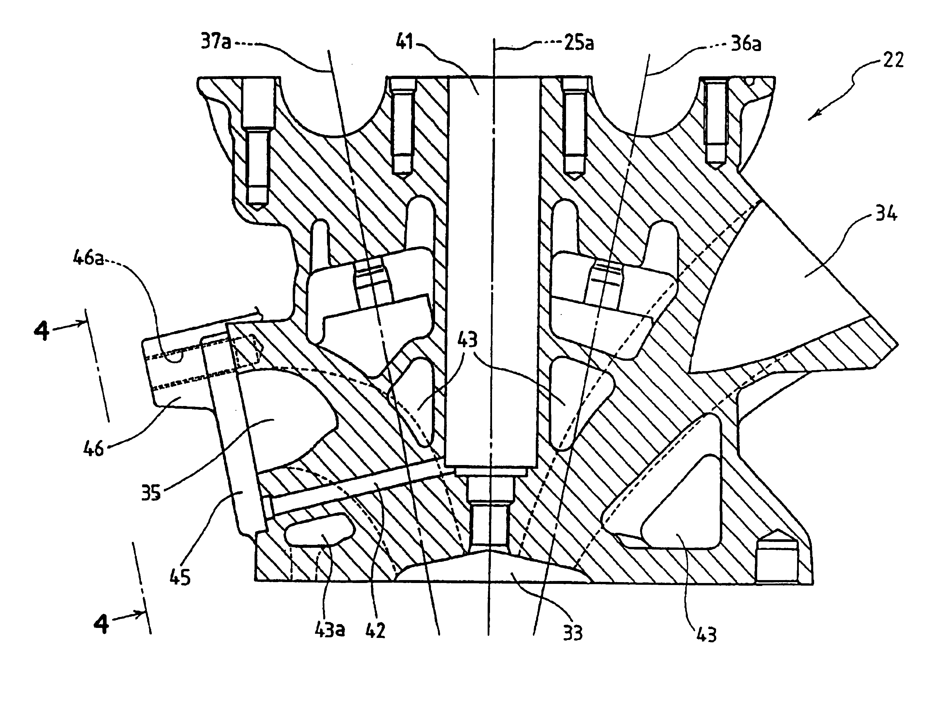
[0007]Since the invention is constituted as mentioned above, it is possible to make the outlet of the water drain hole of the plug hole for mounting the ignition plug opened at a high position of the cylinder head. Accordingly, it is possible to provide the water drain hole at a higher position compared to the conventional cylinder head and hence, a cooling water passage disposed below the water drain hole can be sufficiently enlarged whereby it is possible to make a large quantity of cooling water flow thus enhancing the cooling efficiency of the cylinder head.
[0009]Accordingly, it is possible to make the outlet of the water drain hole of the plug hole for mounting the ignition plug opened at a high position of the cylinder head. Accordingly, it is possible to provide the water drain hole at a higher position compared to the conventional cylinder head and hence, a cooling water passage disposed below the water drain hole can be sufficiently enlarged whereby it is possible to make a large quantity of cooling water flow thus enhancing the cooling efficiency of the cylinder head.
[0010]An outlet of the water drain hole of the plug hole opens in the vicinity of a position below the outlet of the exhaust port. In this manner, the water drain hole of the plug hole is opened in the vicinity of the position below the outlet of the exhaust port and hence, it is possible to provide the water drain hole at a higher position compared to the conventional cylinder head and hence, a cooling water passage disposed below the water drain hole can be sufficiently enlarged whereby it is possible to make a large quantity of cooling water flow thus enhancing the cooling efficiency of the cylinder head.
[0011]Further, an outlet of the water drain hole of the plug hole opens inside a circle which circumscribes an outer periphery of a gasket provided to the outlet of the exhaust port. Accordingly, it is possible to provide the water drain hole at a higher position compared to the conventional cylinder head and hence, a cooling water passage disposed below the water drain hole can be sufficiently enlarged whereby it is possible to make a large quantity of cooling water flow thus enhancing the cooling efficiency of the cylinder head.

Problems solved by technology

Accordingly, a cooling water passage 043a disposed below the water drain hole 042 cannot be enlarged and hence, it is difficult to ensure a sufficient flow of cooling water thus exhibiting the poor cooling efficiency of the cylinder head 022.

Method used


Image

  • Cylinder head of an internal combustion engine
  • Cylinder head of an internal combustion engine
  • Cylinder head of an internal combustion engine

Examples


Embodiment Construction

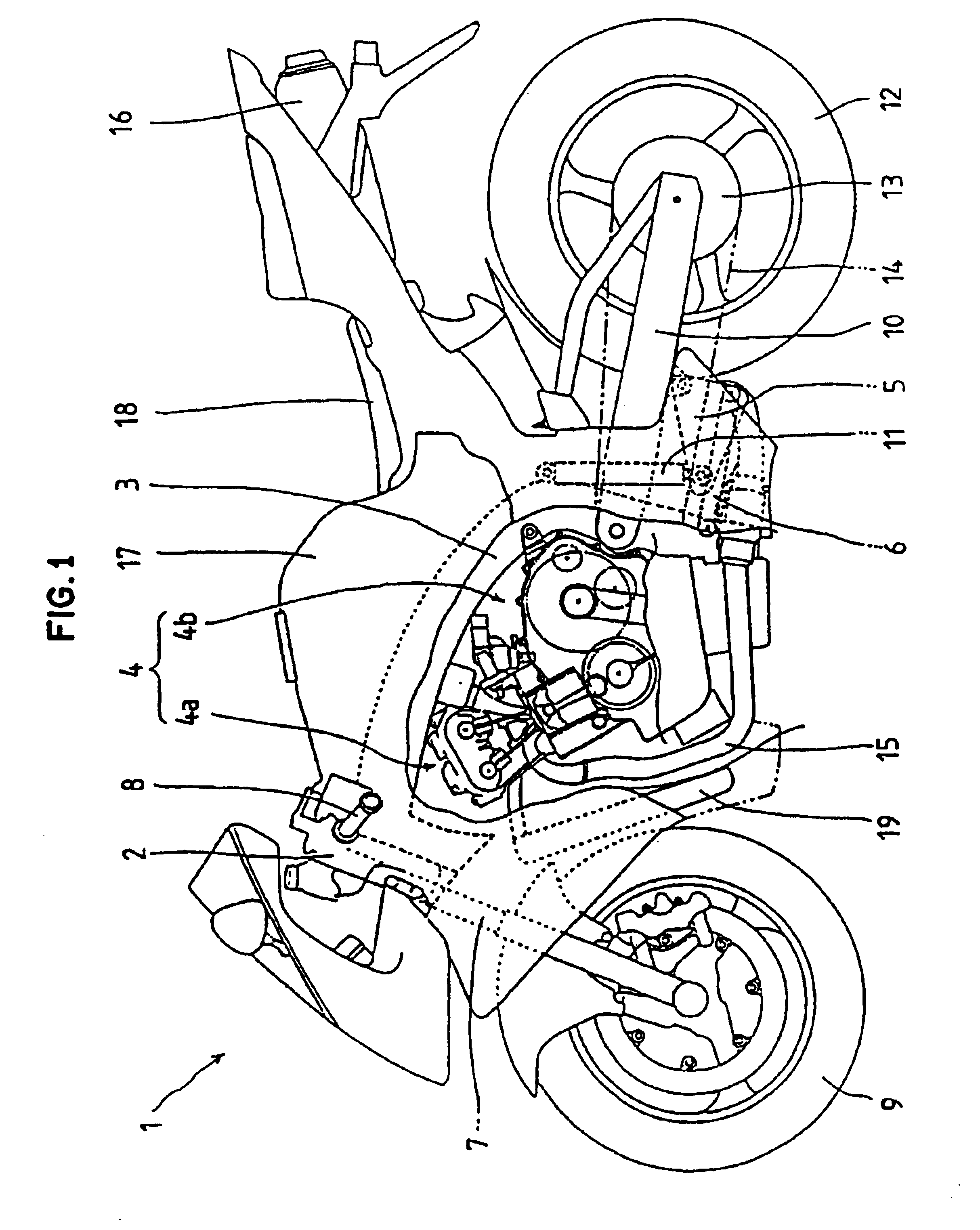
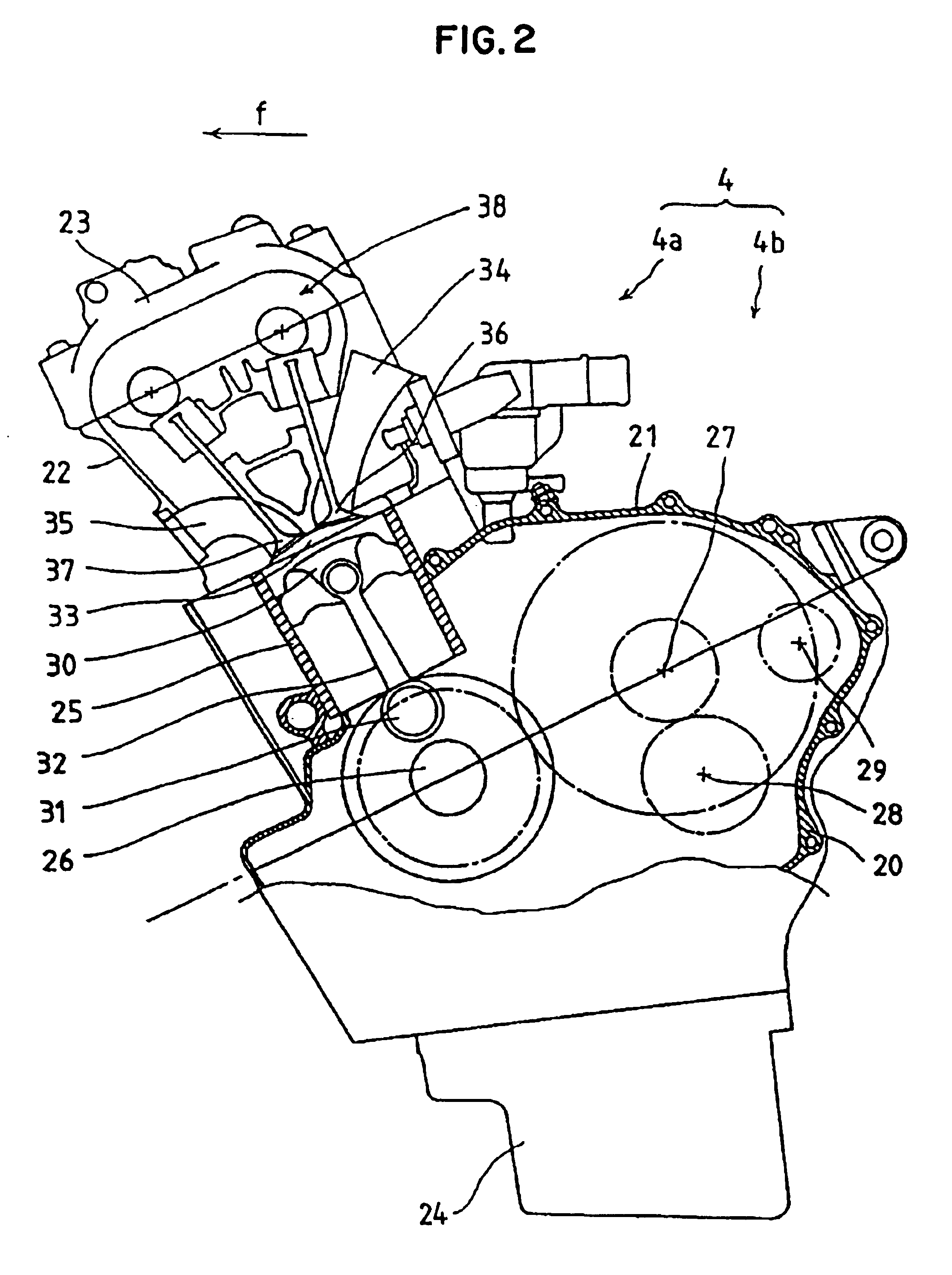
[0022]FIG. 1 is a side view with a part in cross section of a motorcycle 1 on which a water-cooled series 4-cylinder internal combustion engine to which one embodiment of the present invention is applied is mounted. From a vehicle body frame 3 which is contiguously formed with a head pipe 2 of the motorcycle 1, an internal combustion engine 4 which integrally forms a combustion apparatus portion 4a and a transmission portion 4b is suspended. The vehicle body frame 3 is constituted of a plurality of members. A front fork 7 is rotatably supported on the head pipe 2, a steering handle 8 is mounted on an upper end of the front fork 7, and a front wheel 9 is pivotally mounted on a lower end of the front fork 7.

[0023]A rear fork 10 has a front end thereof pivotally supported on a rear portion of the vehicle body frame 3 such that the rear fork 10 is tiltable in the vertical direction. A triangular link member 5 has one corner portion thereof pivotally mounted on a center lower portion of ...


PUM


Abstract

In a cylinder head of an internal combustion engine, a plug hole for mounting an ignition plug is formed along a cylinder axis and an intake port and an exhaust port are respectively formed at both sides of the plug hole while sandwiching the cylinder axis therebetween. The cylinder head further includes an intake valve which opens or closes the intake port and an exhaust valve which opens or closes the exhaust port. In such a constitution, a cross-sectional shape of a flow passage of an outlet of the exhaust port is an oval shape extending in the horizontal direction and a water drain hole of the plug hole is formed below the exhaust port.

Description

FIELD OF THE INVENTION[0001]The present invention relates to a cross-sectional shape of a flow passage of an outlet of an exhaust port of an internal combustion engine and an outlet position of a water drain hole of a plug hole for mounting an ignition plug.BACKGROUND OF THE INVENTION[0002]Conventionally, there has been disclosed a cylinder head of an internal combustion engine in which a plug hole for mounting an ignition plug is formed along a cylinder axis, an intake port and an exhaust port are respectively formed at both sides of the plug hole while sandwiching the cylinder axis therebetween, and an outlet of a water drain hole of the plug hole opens below an outlet of the exhaust port. See, for example, JP-A-7-259641 and JP-A-2002-213334.[0003]FIG. 9 is a longitudinal cross-sectional view showing one example of a cylinder head of a conventional internal combustion engine and FIG. 10 is a view showing a shape of an outlet of an exhaust port of the cylinder head shown in FIG. 9....

Claims


Application Information

Patent Timeline
Patent Type & Authority Patents(United States)
IPC IPC(8): F02F1/38F02F1/42F02F1/26F02P13/00F02F1/24F02F1/36
CPCF02F1/38F02F1/4285F02F1/24F02F1/42
Inventor NAGAHASHI, YOSHIKINAKAGOME, HIROSHI
Owner HONDA MOTOR CO LTD
Learn More