Hyper-cooled liquid-filled transformer

Active Publication Date: 2011-06-16
GUENTERT III JOSEPH J +1
View PDF21 Cites 46 Cited by
  • Summary
  • Abstract
  • Description
  • Claims
  • Application Information

AI Technical Summary

Problems solved by technology

High temperatures for long periods of time in transformers will destroy insulation positioned about and between the windings, thereby leading to a transformer failure.
However, cooling of the dielectric insulating liquid in such a manner is limited by the amount of work it adds to the dielectric liquid to move it out of the insulating/dielectric environment and to the heat exchanger.
That is, the work (e.g., pumping) done on the dielectric liquid can cause frothing and foaming, and if the dielectric liquid is left in this frothed state upon reentry into the transformer, the dielectric strength and heat transfer capability of the liquid will be severely compromised.
Another disadvantage of this type of system is that if the piping between the transformer and the remote heat exchanger were to develop a leak, the amount of insulating li

Method used


Image

  • Hyper-cooled liquid-filled transformer
  • Hyper-cooled liquid-filled transformer
  • Hyper-cooled liquid-filled transformer

Examples


Embodiment Construction

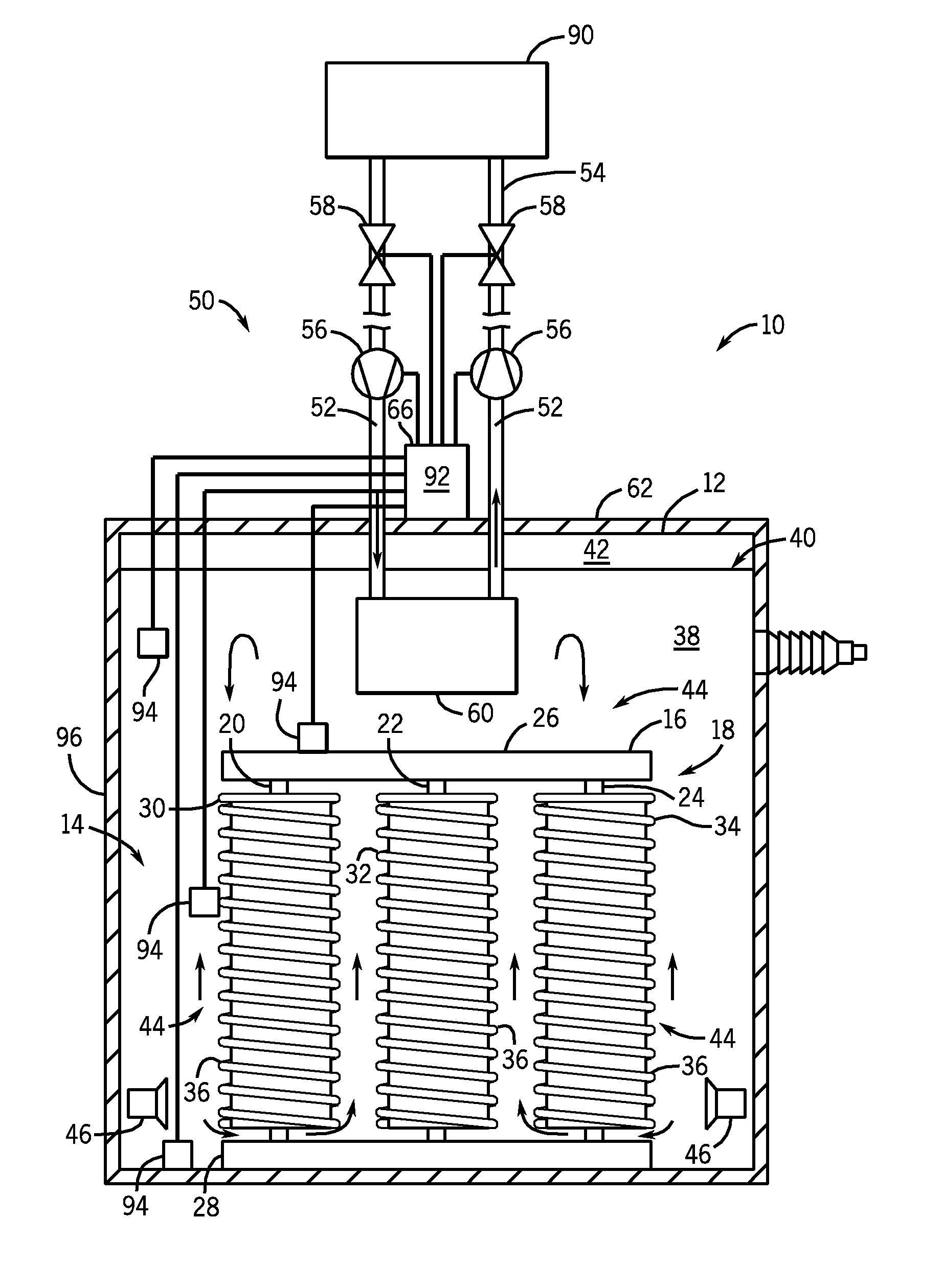
[0028]The operating environment of the invention is described with respect to a liquid-filled transformer. A system is provided for cooling such a liquid-filled transformer so as to minimize externally radiated heat and provide a smaller transformer footprint.

[0029]Referring to FIG. 3, a power transformer 10 is shown according to an embodiment of the invention. The transformer 10 includes a casing or housing 12 (e.g., metallic enclosure) in which is disposed a core-winding assembly 14 formed of a magnetic core 16 with windings 18 there-around. According to an embodiment of the invention, magnetic core-winding assembly 14 includes a three phase magnetic core 16 having, for example, winding legs 20, 22, 24 connected by upper and lower yoke portions 26, 28, respectively. Magnetic core 16 can be formed of a plurality of stacks of magnetic, metallic laminations (not shown), such as grain-oriented silicon steel, for example. While transformer 10 is shown as including a three phase magneti...


PUM


Abstract

A transformer is disclosed that includes a housing having a core-winding assembly positioned therein that is immersed in a dielectric transformer fluid contained within the housing. A cooling system is provided to cool the dielectric transformer fluid contained within the housing and includes a closed-loop fluid path having a quantity of dielectric cooling fluid that is circulated there through and that is maintained separate from the dielectric transformer fluid. A liquid-to-liquid heat exchanger is positioned along the closed-loop fluid path and within the housing so as to be immersed within the dielectric transformer fluid, with the liquid-to-liquid heat exchanger cooling the dielectric transformer fluid based on a liquid-to-liquid transfer of heat energy between the dielectric cooling fluid and the dielectric transformer fluid. The cooling system also includes a heat dissipation system positioned remotely from the liquid-to-liquid heat exchanger to cool the dielectric cooling fluid circulating through the closed-loop fluid path.

Description

CROSS-REFERENCE TO RELATED APPLICATION[0001]The present application is a non-provisional of, and claims priority to, U.S. Provisional Patent Application Ser. No. 61 / 284,001, filed Dec. 10, 2009, the disclosure of which is incorporated herein by reference.BACKGROUND OF THE INVENTION[0002]Embodiments of the present invention relate generally to liquid-filled power transformers, and, more particularly, to a system for cooling such transformers to minimize externally radiated heat, while providing a smaller footprint and thus more options for deploying such a transformer.[0003]Transformers, and similar devices, come in many different shapes and sizes for many different applications and uses. Fundamentally, all of these devices include at least one primary winding(s) with at least one core path(s) and at least one secondary winding(s) wrapped around the core(s). When a varying current (input) is passed through the primary winding a magnetic field is created which induces a varying magnet...

Claims


Application Information

Patent Timeline
IPC IPC(8): H01F27/10
CPCH01F27/12
Inventor GUENTERT, III, JOSEPH J.STEINBRECHER, BRIAN T.
Owner GUENTERT III JOSEPH J
Why Eureka
Try Eureka