
Selective diffractive optical element and a system including the same

a diffractive optical element and selective technology, applied in the field of selective diffractive optical elements and systems, can solve the problems of not being able to guarantee repeated success, not being able to design a new doe and/or replacing the same, and unable to achieve the effect of selective adjustment of optical performan

Inactive Publication Date: 2011-06-16
BROADCOM INT PTE LTD
View PDF5 Cites 7 Cited by
  • Summary
  • Abstract
  • Description
  • Claims
  • Application Information

AI Technical Summary

Benefits of technology

[0007]It is therefore a feature of an embodiment to use of multiple complementary diffractive regions in a DOE to compensate for performance degradations.
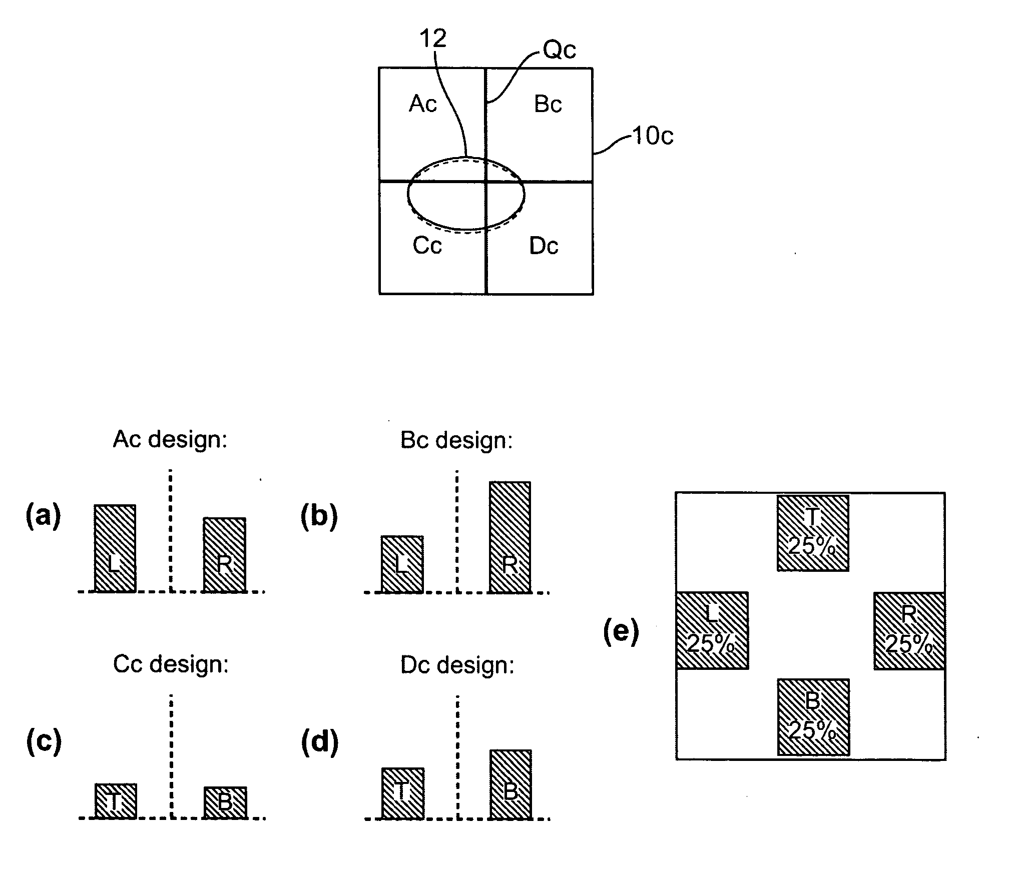
[0009]It is yet another feature of an embodiment to provide a DOE that is segmented in a manner that allows for selective adjustments of optical performance, e.g., tuning or different optical functioning, due to a change in transverse positioning of an illumination beam.

Problems solved by technology

Further, selecting yielded parts to obtain ultra high performance DOEs can be expensive, wasteful, and may not guarantee repeated success.
Additionally, a DOE may be a component in a system having other optical components that degrade over time or having optical requirements that change over time, but designing a new DOE and / or replacing the DOE may not be desirable.

Method used


Image

  • Selective diffractive optical element and a system including the same
  • Selective diffractive optical element and a system including the same
  • Selective diffractive optical element and a system including the same

Examples


Embodiment Construction

[0022]Embodiments will now be described more fully hereinafter with reference to the accompanying drawings, in which exemplary embodiments of the invention are illustrated. The invention may, however, be embodied in different forms and should not be construed as limited to the embodiments set forth herein. Rather, these embodiments are provided so that this disclosure will be thorough and complete, and will fully convey the scope of the invention to those skilled in the art. In the figures, the dimensions of layers and regions may be exaggerated for clarity of illustration.

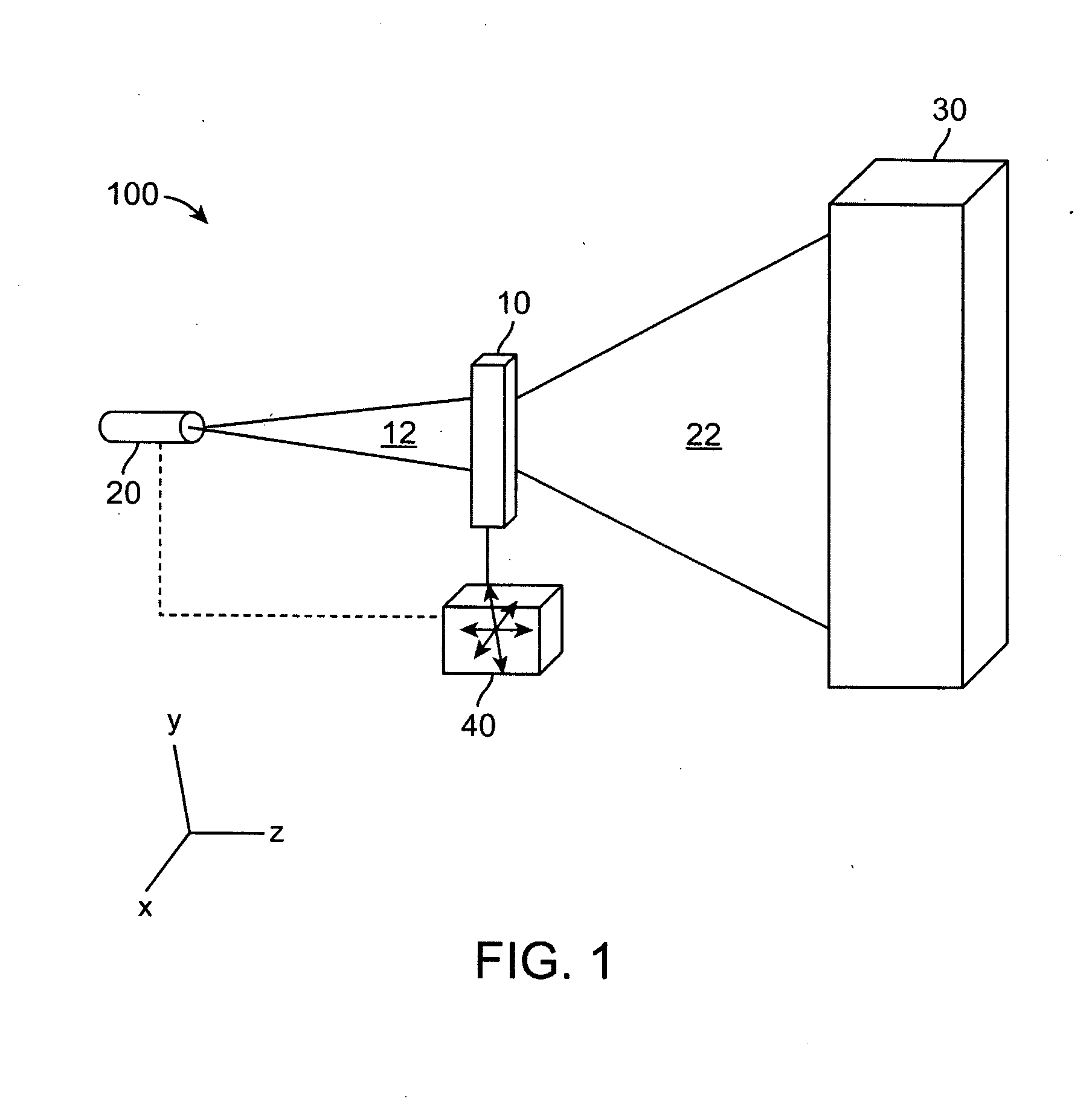
[0023]FIG. 1 illustrates a schematic perspective view of a system 100 including a selective DOE 10 in accordance with embodiments. The system 100 may include a light source 20, the selective DOE 10, and a target 30. The target 30 may be internal to or external to the system 100. The target 30 is illuminated by the DOE 10. At least one of the light source 20, the selective DOE 10, and the target 30 may be movable r...


PUM


Abstract

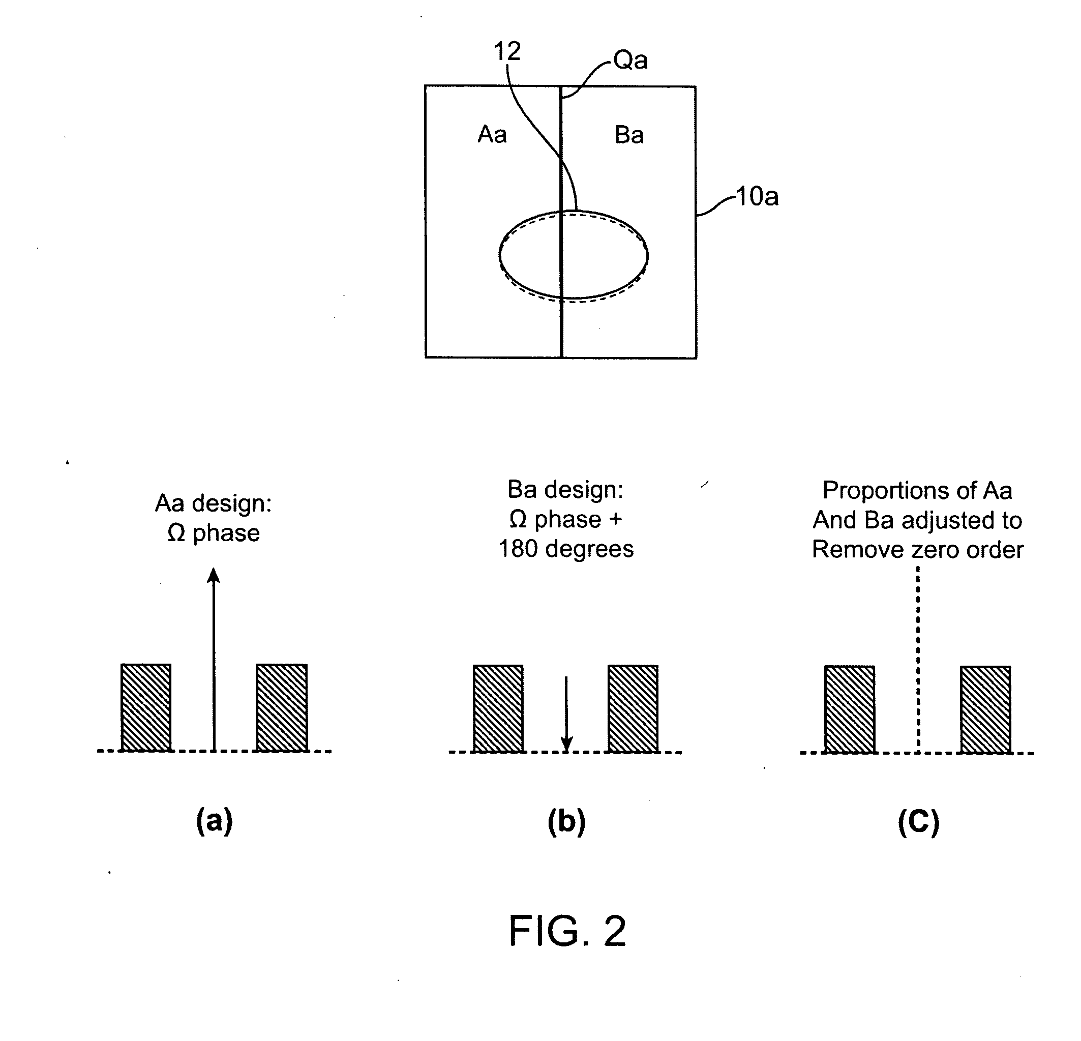
A selective diffractive optical element includes a first diffractive region having a first design on a first surface of a substrate, and a second diffractive region having a second design on the first surface of the substrate, the first and second designs being different, wherein, by altering a position of a cross-section of an illumination beam, the selective diffractive optical element outputs a desired proportion of the two diffractive patterns aligned along an optical axis of the illumination beam.

Description

BACKGROUND OF THE INVENTION[0001]1. Field of the Invention[0002]Embodiments relate to a selective diffractive optical element and a system including the same.[0003]2. Description of the Related Art[0004]Ultra high performance diffractive optical elements (DOEs) have fabrication tolerances that can affect yield. In particular, performance metrics, e.g., zero order, pole balance, intensity distribution, etc., are highly sensitive to any fabrication variation and require precise control. Typically, existing solutions associated with creating a DOE with ultra high performance metrics, e.g., no zero order, perfect pole balance, precise pole intensity distribution, require dialing in a process window during the manufacture of the DOE and / or selecting from yielded DOEs a subset of parts that meet performance specifications. However, dialing in process windows to provide ultra high performance requires a matrix of varied parts, time, proper measurement and assessment, and high performance t...

Claims


Application Information

Patent Timeline
Patent Type & Authority Applications(United States)
IPC IPC(8): G02B5/18
CPCG02B5/1819G02B27/0944G03F7/70158G03F7/70108G02B27/4238
Inventor STACK, JAREDKATHMAN, ALAN
Owner BROADCOM INT PTE LTD
Learn More