Self-calibration circuit and method for junction temperature estimation

a self-calibration circuit and junction temperature technology, applied in the direction of instruments, heat measurement, calorimeters, etc., can solve the problems of adding cost, effort, complexity, etc., and achieve the effect of accurate and fast junction temperature measuremen

Inactive Publication Date: 2011-06-23
NXP BV
View PDF7 Cites 74 Cited by
  • Summary
  • Abstract
  • Description
  • Claims
  • Application Information

AI Technical Summary

Benefits of technology

[0008]It is an object of the present invention to provide a calibrating circuit and method to be ...

Problems solved by technology

However, this predetermination of reference values add c...

Method used


Image

  • Self-calibration circuit and method for junction temperature estimation
  • Self-calibration circuit and method for junction temperature estimation
  • Self-calibration circuit and method for junction temperature estimation

Examples


Embodiment Construction

[0031]The present invention is further elucidated by the following figures and examples, which are not intended to limit the scope of the invention. The person skilled in the art will understand that various embodiments may be combined.

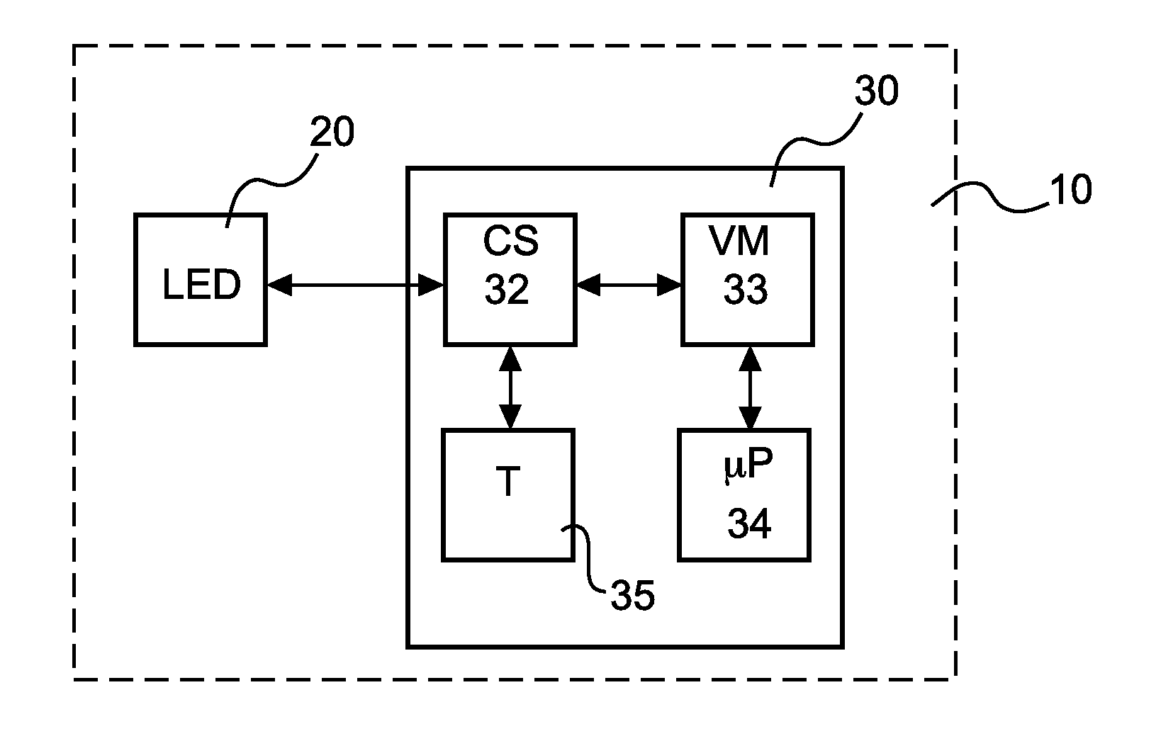
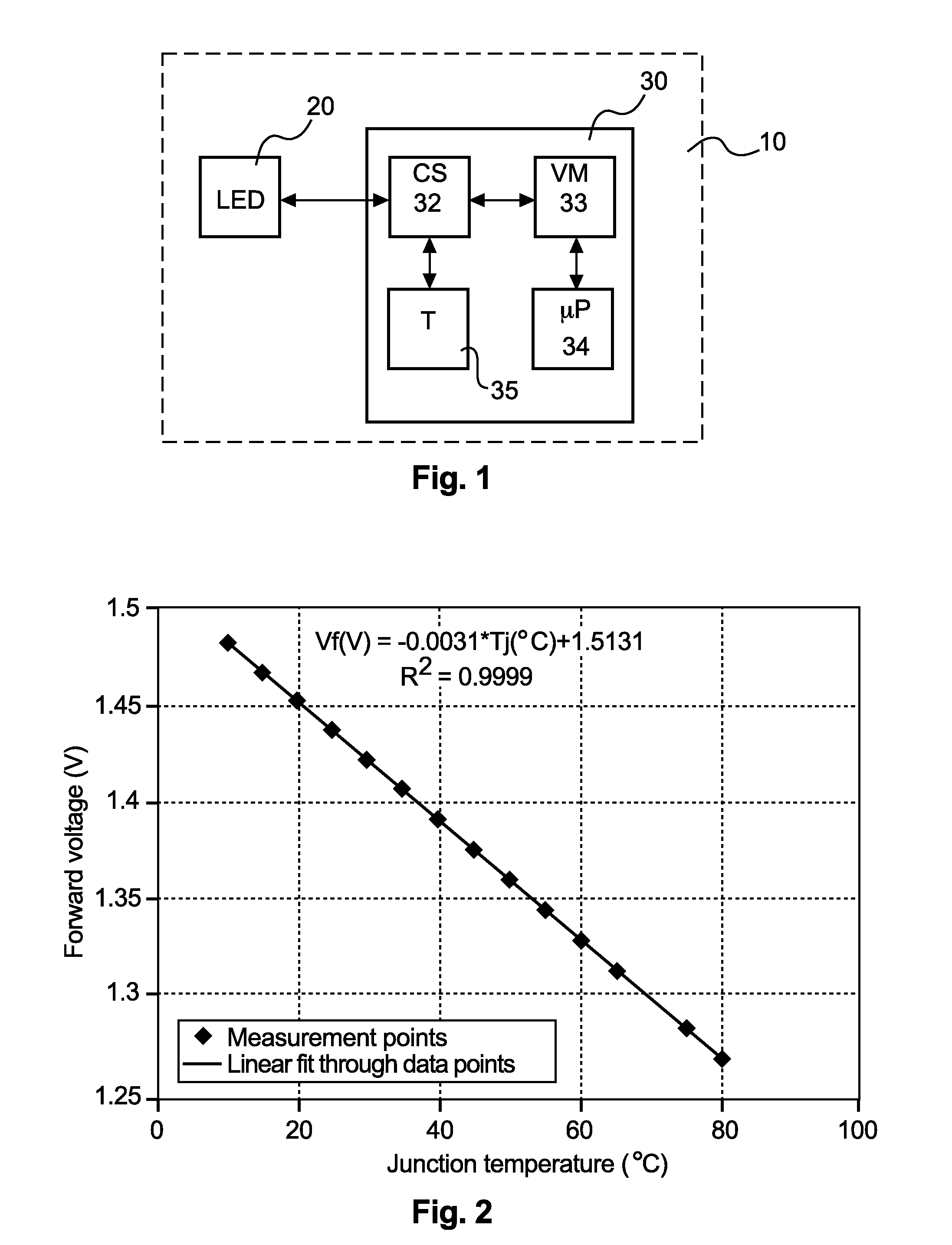
[0032]FIG. 1 shows a schematic block diagram of a self-calibrating circuit 30 according to an embodiment. The self-calibrating circuit 30 is connected to an LED 20 so as to control the calibration process. An automatic calibration of the LED 20 for temperature sensing is achieved by using a standard, build-in temperature sensor 35 in the calibration circuit 30. The dashed box, drawn around the LED 20 and the calibration circuit 30, indicates a common ambient environment 10, which ensures that the LED 20 and the calibration circuit 30 are substantially at the same temperature.

[0033]Additionally, the calibration circuit 30 includes a current source (CS) 32, a voltage measurement block (VM) 33, and a microcontroller or microprocessor (μP) 34 with embedde...


PUM


Abstract

The present invention relates to a calibration circuit, computer program product, and method of calibrating a junction temperature measurement of a semiconductor element, wherein respective forward voltages at junctions of the semiconductor element and a reference temperature sensor are measured, and an absolute ambient temperature is determined by using the reference temperature sensor, and the junction temperature of the semiconductor element is predicted based on the absolute ambient temperature and the measured forward voltages.

Description

[0001]This application claims the priority under 35 U.S.C. §119 of European patent application no. 09179980.9, filed on Dec. 18, 2009, the contents of which are incorporated by reference herein.FIELD OF THE INVENTION[0002]The present invention relates to a calibration circuit, method and computer program product for calibrating a junction temperature measurement of a semiconductor element, such as—but not limited to—a light emitting diode (LED).BACKGROUND OF THE INVENTION[0003]High intensity LEDs are becoming more popular as light sources for traffic lights, automobile interior and exterior lighting, signboards, and other applications. The light output of a silicon LED chip is not only a function of the chip size and the process, but also a function of the junction temperature of the LED. By keeping the junction temperature low, LEDs can be driven with twice or three times as much current and, thus, generate twice or three times the light output while still extending the life of the...

Claims


Application Information

Patent Timeline
IPC IPC(8): G01K15/00
CPCG01K7/01H05B33/089G01K15/00H05B45/56
Inventor NGUYEN HOANG, VIETBANCKEN, PASCALSURDEANU, RADUBATAILLOU, BENOITSTEENWINCKEL, DAVID VAN
Owner NXP BV
Why Eureka
Try Eureka