Electrical card connector

Inactive Publication Date: 2011-06-23
HON HAI PRECISION IND CO LTD
View PDF1 Cites 6 Cited by
  • Summary
  • Abstract
  • Description
  • Claims
  • Application Information

AI Technical Summary

Benefits of technology

[0007]Accordingly, an object of the present invention is to provide an el

Problems solved by technology

The own capacity of the electronic products are not large enough for memorizing so such information.
Because the pivot engages rigid inner walls of th

Method used


Image

  • Electrical card connector
  • Electrical card connector
  • Electrical card connector

Examples


Example

[0014]Reference will now be made in detail to the preferred embodiment of the present invention.

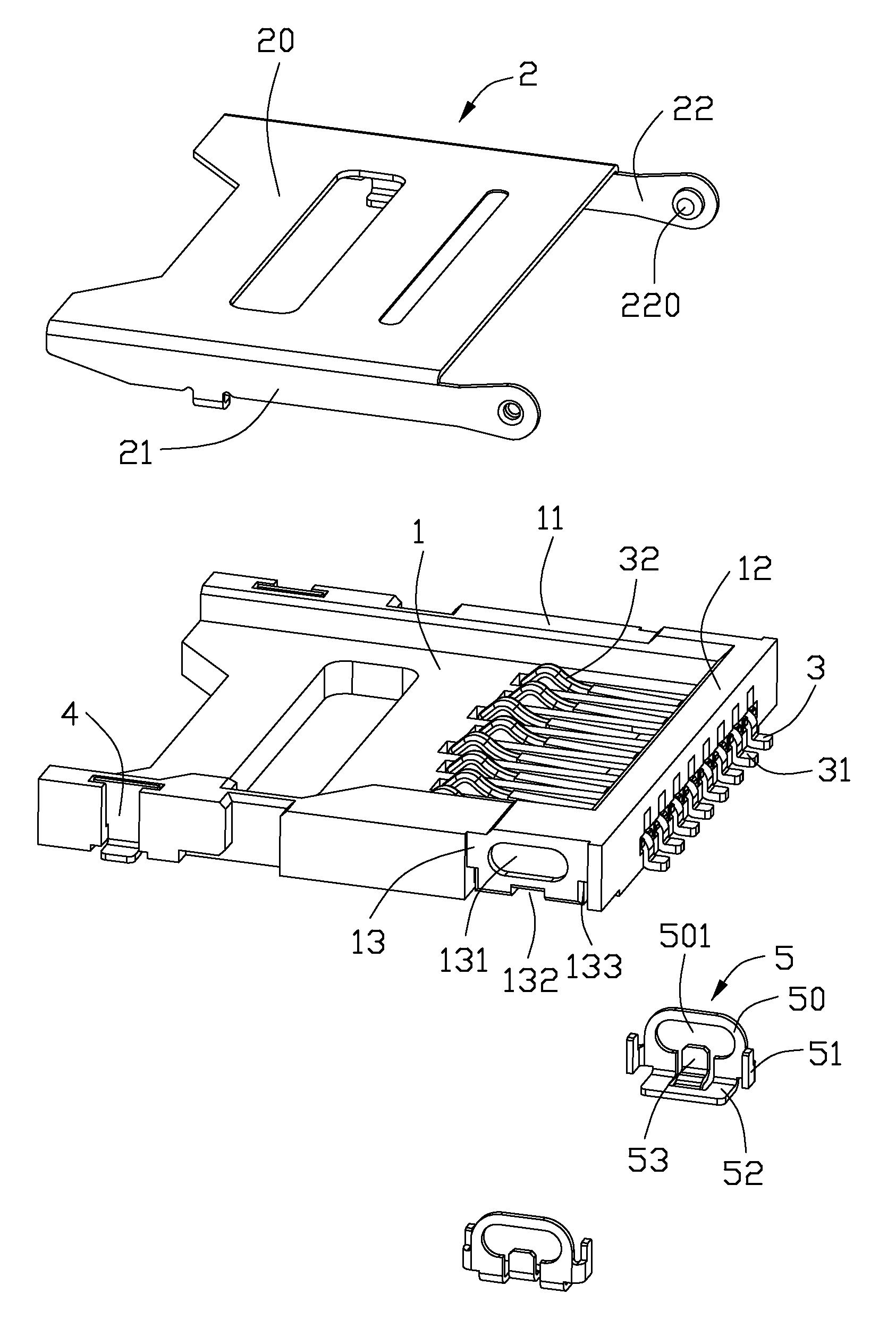
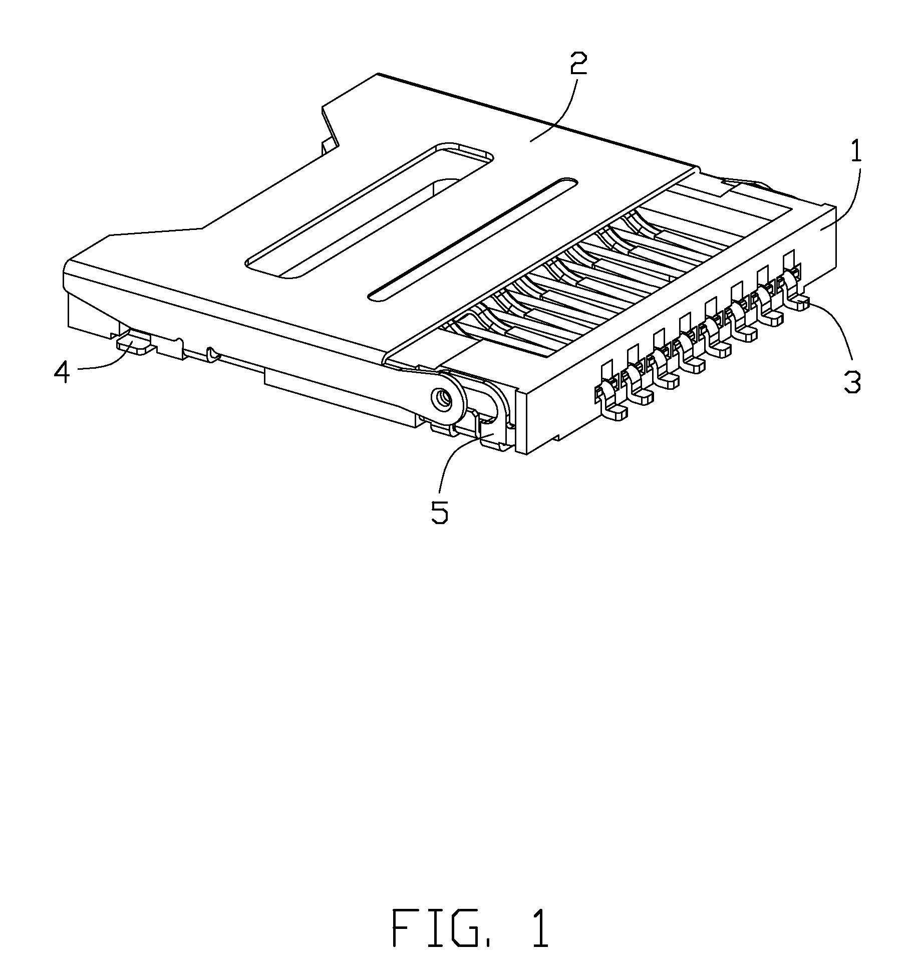
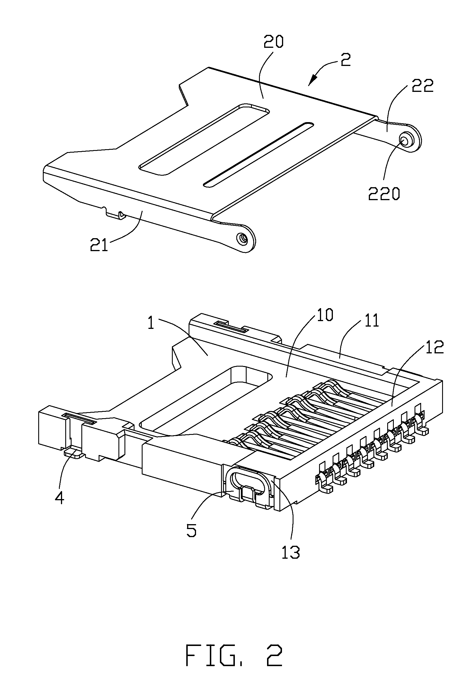
[0015]Referring to FIGS. 1-4, an electrical card connector (not labeled) in accordance with the present invention, comprises an insulative housing 1, a plurality of contacts 3 retained in the insulative housing 1, a metallic shell 2 pivotally covering the insulative housing 1, a pair of fixing pads 4 and a pair of metal pads 5 assembled at opposite ends of the insulative housing 1. The fixing pads 4 and the metal pads 5 are adapted for soldering a printed circuit board (not shown) and therefore, the insulative housing 1 is positioned on the printed circuit board.

[0016]Referring to FIGS. 2-3, the insulative housing 1 comprises a base portion 10, a pair of side walls 11 extending upwardly from the base portion 10, and a rear wall 12 connecting with the side walls 11. The contacts 3 are retained in the insulative housing 1, having a plurality of contacting portions 32 extending beyond the ba...


PUM


Abstract

An electrical card connector includes an insulative housing (1), a number of contacts (3) assembled in the insulative housing, a pair of metal pads (5) assembled to the side walls of the insulative housing, and a metallic shell (2). The insulative housing has a base portion (10) and a pair of side walls (11) extending from the base portion. Each metal pad has a cavity (501) and an elastic tongue portion (53) extending into the cavity. The metallic shell forms a pair of pivots (220) extending through and movable in the cavity. The elastic tongue portion is resiliently engageable with the pivot in response to a movement of the pivot along an inner edge of the cavity.

Description

BACKGROUND OF THE INVENTION[0001]1. Field of the Invention[0002]The present invention relates generally to an electrical card connector, and more particularly to an electrical card connector more conveniently operated by a user when the user pivotally assembles the shell to the insulative housing.[0003]2. Description of Related Arts[0004]According to rapid developments of electronic products, such as mobile phones, digital cameras, etc, the electronic products are multi-functioned to meet with different requirements of customers. The own capacity of the electronic products are not large enough for memorizing so such information. External, portable electrical cards are invented for adding capacity of the electronic products and accordingly, electrical card connectors are popularly assembled on printed circuit boards of the electronic products for receiving the electrical cards. The electrical card connectors transmit signals between the electrical cards and the electronic products.[0...

Claims


Application Information

Patent Timeline
IPC IPC(8): H01R24/00
CPCH01R12/707H01R12/88H01R12/716
Inventor ZHANG, WEI-DE
Owner HON HAI PRECISION IND CO LTD
Why Eureka
Try Eureka