System and method for activating an isolated device

a technology of isolated devices and activation methods, which is applied in the direction of contact mechanisms, cell components, cell component details, etc., can solve the problems of preventing the activation of the discharge circuit, the removal of the pull-tab fails to activate the circuit, and the cell has limited protection from the ambient environment, so as to reduce the power available to operate the device. , the effect of reducing the need

Active Publication Date: 2011-06-30
ULTRALIFE CORPORATION
View PDF18 Cites 12 Cited by
  • Summary
  • Abstract
  • Description
  • Claims
  • Application Information

AI Technical Summary

Benefits of technology

[0008]In accordance with an aspect of the present disclosure, the use of an external non-mechanical stimuli, such as external fields (e.g., magnetic fields) provides for remote activation for controlling the state of a CDD located within a sealed battery housing. In one example an electro or permanent magnetic field source is directed through a non-ferrous region of a battery housing to activate the operation of an internal circuit, CDD and/or state of charge indicators, for example. Accordingly, the magnetic field is encouraged to permeate the outer housing and thereby mitigate the need to physically pass through the housing to activate a discharge circuit.
[0009]In one embodiment, magnetic field sensors may include non-contact sensing devices based on the Hall-effect principle, whereby a voltage differential is sense...

Problems solved by technology

The absence of a CDD often necessitates a disposal process including costly procedures for the handling and disposition of hazardous waste materials.
For instance, if the spring contact loses its bias, the removal of the pull-tab would fail to activate the circuit.
A further potential problem, when using a tab or material between the contacts, is that residual material, oxidation and/or corr...

Method used


Image

  • System and method for activating an isolated device
  • System and method for activating an isolated device
  • System and method for activating an isolated device

Examples


Embodiment Construction

[0025]For a general understanding of the embodiments, reference is made to the drawings. In the drawings, like reference numerals have been used throughout to designate identical or equivalent elements. It is also noted that the various drawings illustrating the embodiments are not drawn to scale and that certain regions may have been purposely drawn disproportionately so that the features and concepts disclosed herein may be properly illustrated.

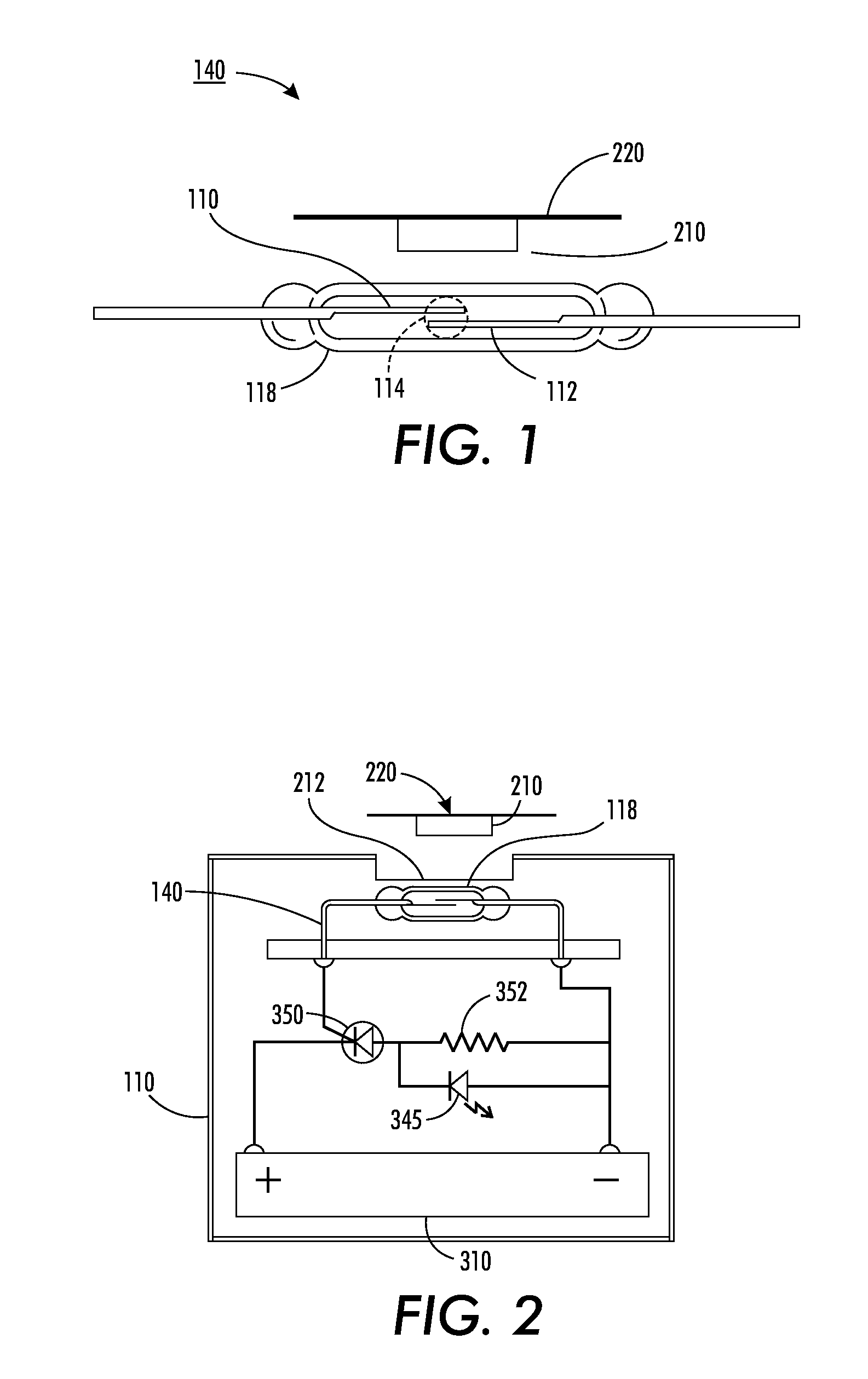
[0026]Referring to FIG. 1, there is shown an example of a magnetic field source 210 in relation to a sensor or switch 140. Although various magnetic materials may be employed as the source of the magnetic field, it is believed that commonly available ferromagnetic materials (e.g., iron, nickel, cobalt) have a suitable flux density and coercive force for non-mechanical activation of a switch component. The arrangement of the magnet assembly, depicted in FIG. 1, is a thin, possibly flexible strip of ferromagnetic material mounted or affixed t...


PUM


Abstract

Disclosed is a system and method for controlling the activation of isolated circuitry, and more particularly complete discharge devices for batteries, and similar circuits that are enclosed within sealed housings.

Description

[0001]This application claims priority under 35 U.S.C. §119, from U.S. Provisional Application No. 61 / 291,414 for “SYSTEM AND METHOD FOR ACTIVATING AN ISOLATED DEVICE,” filed on Dec. 31, 2009 by Kyle Karren and Athanasios Gkourlias, which is hereby incorporated by reference in its entirety.[0002]The present disclosure is directed to controlling a device / circuit contained within a hermetically sealed unit using a non-mechanical stimuli, and more particularly controlling a complete discharge circuit within a sealed housing, in order to neutralize a battery's potential using a non-contact external actuation.BACKGROUND & SUMMARY OF DISCLOSURE[0003]A complete discharge device (CDD) generally consists of a resistive load component and an activation component to complete a resistive short circuit between the terminals of a battery, for the purpose of discharging residual power. The incorporation of a CDD into a lithium battery is primarily intended to expend the residual energy remaining i...

Claims


Application Information

Patent Timeline
IPC IPC(8): H01H33/59H01M50/202H01M50/24H01M50/296
CPCH01M2/1022H01M10/052H01H36/0006H01M10/48Y02E60/10H01M50/202H01M50/296H01M50/24
Inventor KARREN, KYLEGKOURLIAS, ATHANASIOS
Owner ULTRALIFE CORPORATION
Why Eureka
Try Eureka