Three-dimensional video transmission system, video display device and video output device

a video transmission system and video display technology, applied in the field of three-dimensional video image transmission system, video image display device and video image output device, can solve the problems of inability to communicate video and audio data in formats that are not incompatibility with each other, and the connection between the devices for transmitting three-dimensional video images

Inactive Publication Date: 2011-06-30
PANASONIC CORP
View PDF11 Cites 26 Cited by
  • Summary
  • Abstract
  • Description
  • Claims
  • Application Information

AI Technical Summary

Benefits of technology

[0015]Such a configuration allows the video image output device to acquire information on the display capability of the display device through HDMI, which enables transmitting three-dimensional video image data adapted to the display device.

Problems solved by technology

Hence, video and audio data in formats incompliant with each other cannot be communicated successfully.
However, with conventional methods including that in patent literature 1, transmission of three-dimensional video images is not considered, thus leaving disadvantages in connecting between devices for transmitting three-dimensional video images.

Method used


Image

  • Three-dimensional video transmission system, video display device and video output device
  • Three-dimensional video transmission system, video display device and video output device
  • Three-dimensional video transmission system, video display device and video output device

Examples


first exemplary embodiment

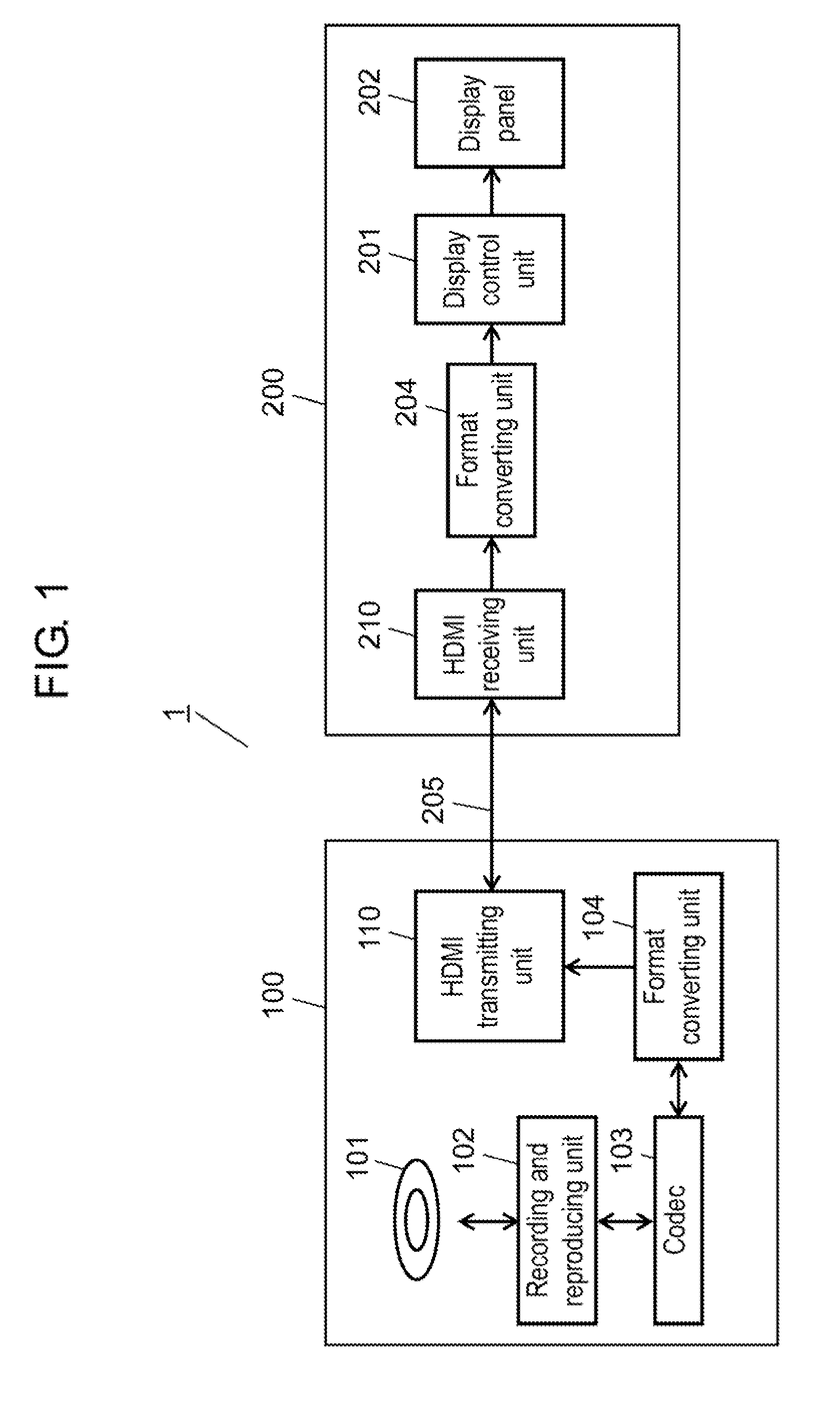
[0043]FIG. 1 shows a configuration example in a three-dimensional video image transmission system for transmitting three-dimensional video images (hereinafter, also referred to as 3D (dimensional) video image), according to the embodiment. In FIG. 1, three-dimensional video image transmission system 1 includes: video image recording and reproducing device (hereinafter, abbreviated as recording and reproducing device) 100 as a video image output device capable of reproducing three-dimensional video images; and video image display device (hereinafter, abbreviated as display device) 200 capable of displaying three-dimensional video images. Recording and reproducing device 100 and display device 200 are connected with HDMI cable 205.

[0044]Recording and reproducing device 100, which is a DVD recorder for example, includes optical disc 101, recording and reproducing unit 102, codec 103, format converting unit 104, and HDMI transmitting unit 110. Compressed 3D video image data, compressed ...

second exemplary embodiment

[0102]Next, a description is made of the second exemplary embodiment of the present invention using FIG. 14. FIG. 14 shows a configuration example of three-dimensional video image transmission system 2 according to the embodiment. System 2 is different from the first embodiment in that the video image output device has been changed from recording and reproducing device 100 to tuner 300. The other components are the same as those of the first embodiment, and thus the same component is given the same reference mark to omit its description.

[0103]Tuner 300 as a video image receiving device includes receiving unit 305, format converting unit 304, and HDMI transmitting unit 310, and is connected to antenna 301, coaxial cable 302, and Internet 303. 3D video images broadcast from a broadcasting station (not shown) are received by receiving unit 305 (i.e. a video image acquiring unit) through antenna 301 in a predetermined receiving format. The 3D video images received are converted into a t...


PUM


Abstract

In a recording and reproducing device, compressed 3D video image data recorded on an optical disc is reproduced by a recording and reproducing unit and decompressed to baseband 3D video image data by a codec. A format converting unit converts the recording format of the optical disc into the transmission format of HDMI in accordance with the display capability of the display device preliminarily acquired and outputs the resulting data. The format converting unit of the display device converts the transmission format of 3D video image data received through an HDMI cable into a display format. A display control unit displays 3D video image data converted into the display format on the display panel.

Description

TECHNICAL FIELD[0001]The present invention relates to a three-dimensional video image transmission system, and a video image display device and a video image output device composing the system, particularly to those transmitting three-dimensional video images through an interface compliant with the HDMI standard.BACKGROUND ART[0002]Conventionally, various types of methods have been devised for stereovision of TV images. These methods, using binocular parallax. alternately present right- and left-eye images specially or temporally on a single display, to provide three-dimensional images when viewed by a viewer wearing special glasses or with the naked eye.[0003]Recently, devices have been widely used with HDMI (High Definition Multimedia Interface) terminals compliant with the HDMI standard. For example, connecting a TV to a DVD recorder with an HDMI connecting cable allows sending and receiving high-quality video and audio data as well as some types of control information between th...

Claims


Application Information

Patent Timeline
Patent Type & Authority Applications(United States)
IPC IPC(8): H04N13/00H04N13/04G09G5/00G09G5/36G09G5/391H04N5/765H04N5/92H04N7/173H04N21/436H04N21/442
CPCH04N5/775G09G2370/12H04N9/8227H04N13/0029H04N13/0059H04N21/4122H04N21/42646H04N21/4325H04N21/43632H04N21/4402H04N19/597G09G3/003G09G5/006G09G2370/047H04N5/85H04N13/194H04N13/139
Inventor MITANI, HIROSHINISHIO, TOSHIROH
Owner PANASONIC CORP
Why Eureka
Try Eureka