
Turn-indicator light module for a vehicle mirror assembly and vehicle mirror assembly comprising a turn-indicator light module

a technology of turn-indicator light and vehicle mirror, which is applied in the direction of optical viewing, lighting and heating equipment, transportation and packaging, etc., can solve the problems of uniform light distribution and blending effects, drivers and pedestrians blending effects, etc., and achieve the effect of fast and easy maintenance and repair of the mirror, saving time and money

Active Publication Date: 2011-06-30
SMR PATENTS S A R L
View PDF4 Cites 30 Cited by
  • Summary
  • Abstract
  • Description
  • Claims
  • Application Information

AI Technical Summary

Benefits of technology

[0011]It is an object of the invention to provide an improved and compact turn-indicator light module for an external rear view mirror assembly of a vehicle which does not generate blending effects, has a uniform light distribution and can be recognized in different directions with the same brightness and quality. Another object of the invention is to provide a vehicle mirror assembly comprising a non-blending and uniform light distributing turn-indicator light module.

Problems solved by technology

Directly emitted light can cause blending effects to drivers and pedestrians and suffers from a non-uniform light distribution such that the turning light signal can not be seen in all directions with a uniform intensity and brightness.
The light emitting sources emit light directly towards the surrounding traffic, using light guiding elements and one or several lenses cause non-uniform light distribution and blending effects.

Method used


Image

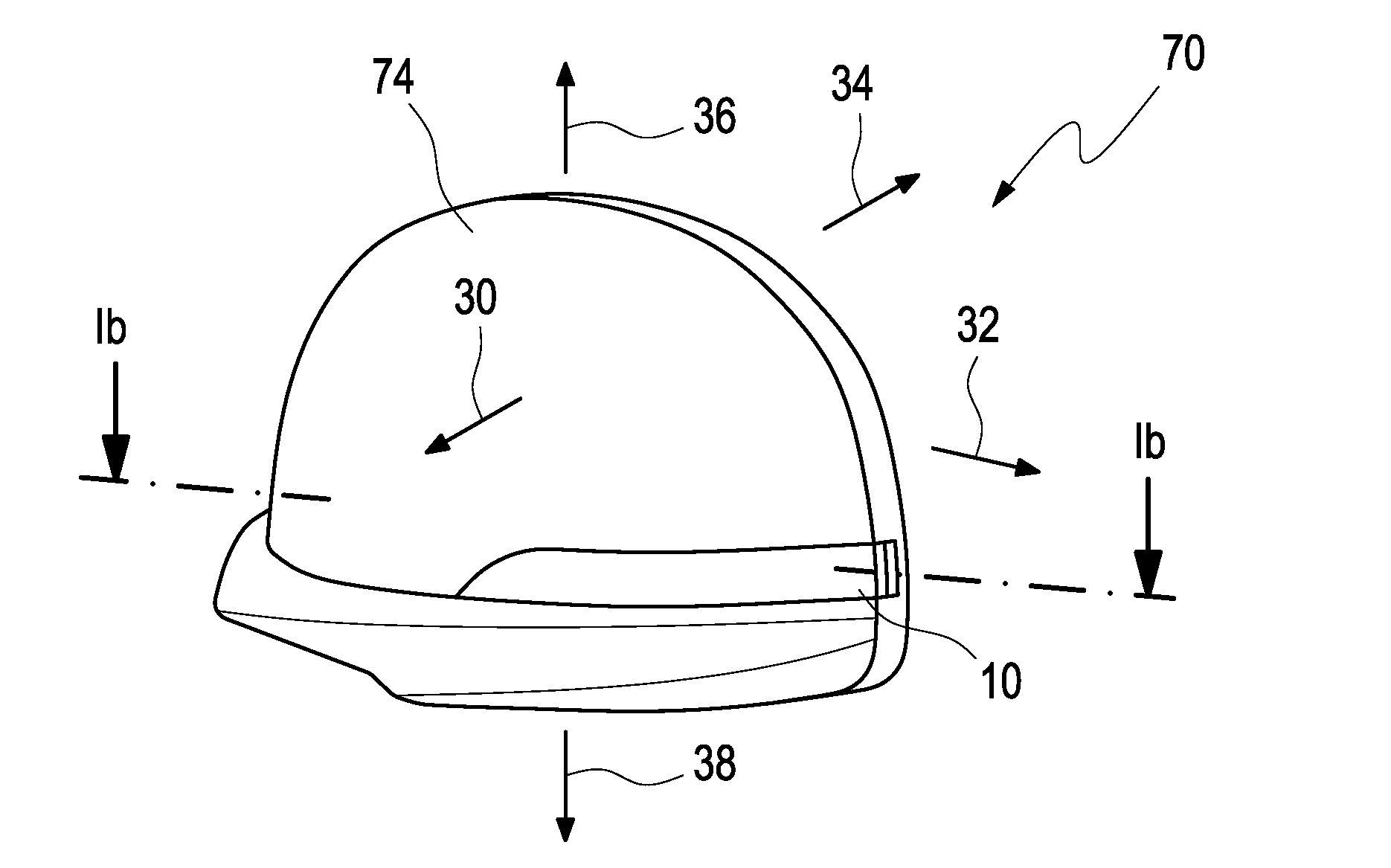
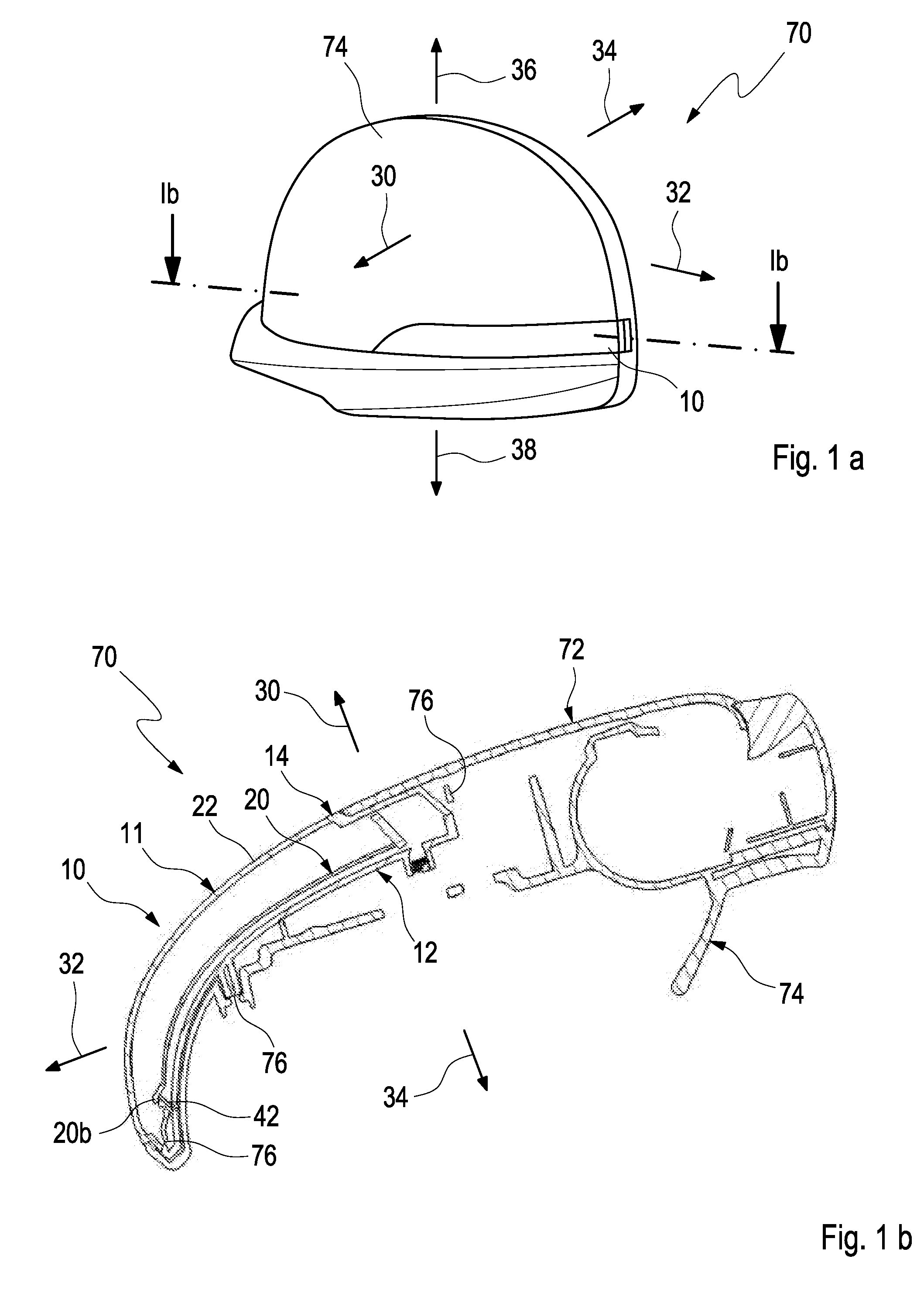
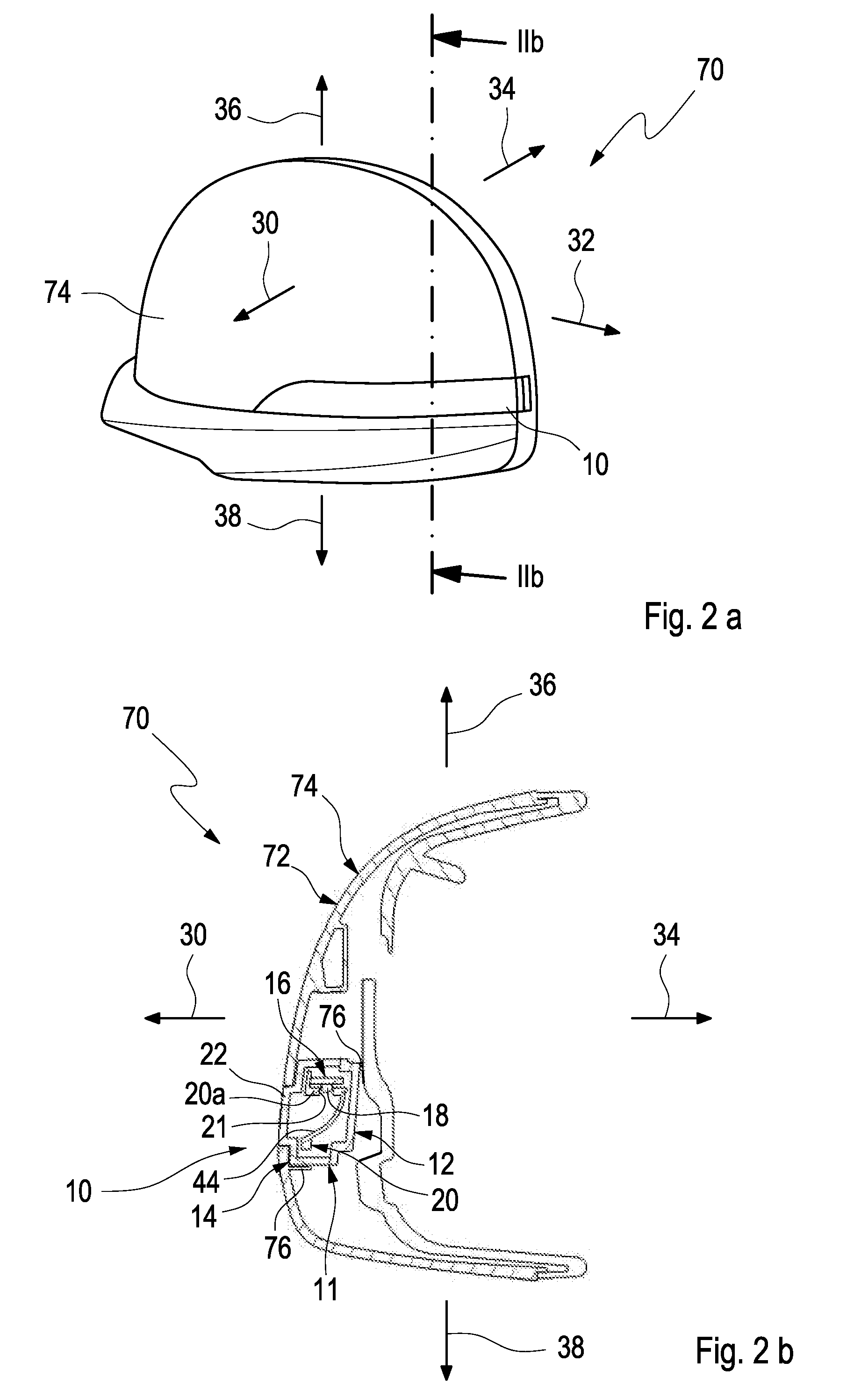
  • Turn-indicator light module for a vehicle mirror assembly and vehicle mirror assembly comprising a turn-indicator light module
  • Turn-indicator light module for a vehicle mirror assembly and vehicle mirror assembly comprising a turn-indicator light module
  • Turn-indicator light module for a vehicle mirror assembly and vehicle mirror assembly comprising a turn-indicator light module

Examples


first embodiment

[0061]FIG. 5 shows a schematic representation of the first embodiment light emission the rear view mirror assembly 70 according to the invention with the turn-indicator light module 10 having an even, smooth reflecting surface 44 of the reflector unit 20. Contrariwise, FIG. 6 shows a variant with the turn-indicator light module 10 having a ruffled reflecting surface 44 of the reflector unit 20 with grooves 50 in the reflecting surface. The light rays 68 reflected from the reflector surface 44, forming indirectly emitted light rays, are indicated by bent arrows.

[0062]FIGS. 7a, 7b depicts a schematic representation of light emission of the external rear view mirror assembly 70 comprising a turn-indicator light module according to the first example embodiment of the invention in a zoomed view (FIG. 7a) and in a top view (FIG. 7b). The indirectly emitted light rays 68 point in driving direction 30 in a generally forward direction. A small portion of the light can leave the external rear...

second embodiment

[0066]FIGS. 9a, 9b display another perspective view (FIG. 9a) of the rear view mirror assembly 70 and a cross-sectional cut through the rear view mirror assembly 70 (FIG. 9b). The lens portion 22 fills the empty space between the outer surface 52 of the lens portion 22 and the reflecting surface 44 of the reflector unit 20 leaving only a small air gap 60 between the inner surface 54 of the lens portion 22 and an inner surface 56 of the reflector unit 20. The reflector unit 20 is made of massive material like the lens portion 22. Either the inner surface 54 of the lens portion 22 or the inner surface 56 of the reflector unit 20 may by metallized for acting as reflecting surface 44.

[0067]The lens portion 22 has a recess 62 for each light emitting source 18. Light from the light emitting source 18 enters into the lens portion 22 and is reflected from the reflecting surface 44 in the desired direction.

[0068]The reflector unit 20 may now be integral part of the rear housing unit 12 which...


PUM


Abstract

A turn-indicator light module for an external rear view mirror assembly has at least one or more light emitting sources mounted on one or more printed circuit boards (PCBs). A reflector and a front housing unit create a lens. At least a major portion of the light module follows a portion of said outer contour of the mirror assembly in the driving direction. The PCB is arranged with respect to the reflector to emit light indirectly by light reflection by the reflector along the major portion of the lens portion of the front housing unit.

Description

[0001]The invention is based on a priority patent application EP 09016089.6 which is hereby incorporated by reference.BACKGROUND ART[0002]1. Field of the Invention[0003]The invention pertains to a turn-indicator light module for a vehicle mirror assembly. More particularly, the invention pertains to a vehicle mirror assembly having a turn-signal light module having at least one light source directly away from the side of the motor vehicle.[0004]2. Description of the Related Art[0005]Modern vehicles are equipped with different turn indicator light modules for signaling a turn maneuver to neighboring drivers thus enhancing passive safety of the vehicle and the surrounding traffic. For instance multiple forward and backward directed turn indicator lights and also separate sideward directed turn indicator lights signal an intended turn maneuver of a vehicle to following vehicles, oncoming vehicles and pedestrians so that they are prepared for a sudden driving direction change of the veh...

Claims


Application Information

Patent Timeline
Patent Type & Authority Applications(United States)
IPC IPC(8): B60Q1/26
CPCB60R1/1207B60Q1/2665F21V7/04
Inventor HWANG, HYOK-JOOPARK, KWANG-RYEOL
Owner SMR PATENTS S A R L
Learn More