
Developing apparatus and image forming apparatus

a technology of developing apparatus and image forming apparatus, which is applied in the direction of electrographic process apparatus, instruments, optics, etc., can solve the problems of inability to accurately detect the change in the amount of toner charged in the developer, the inability of the developer to change in apparent magnetic permeability, and the inability to accurately detect the change in the amount of toner in the developer provided by the developer container with a magnetic permeability sensor. to achieve the effect of accurate detection of changes

Inactive Publication Date: 2011-06-30
CANON KK
View PDF5 Cites 6 Cited by
  • Summary
  • Abstract
  • Description
  • Claims
  • Application Information

AI Technical Summary

Benefits of technology

[0010]Thus, the primary object of the present invention which was made in consideration of the above described matters is to provide a developing apparatus capable of accurately detecting the changes which occurred to the developer in its developer container due to the changes in the ambience of the developer, and an image forming apparatus equipped with such a developing apparatus.

Problems solved by technology

On the other hand, it is very difficult to accurately detect the changes in the amount of toner charge.
However, as the toner particles in developer change in the amount of electric charge, the developer particles change in the amount of force by which they repel among themselves, and therefore, the developer changes in the particle gap, that is, it increases in apparent density, which causes the developer to change in apparent magnetic permeability.
In other words, it is possible that the amount of toner in developer detected by providing a developer container with a magnetic permeability sensor may not be accurate.
This is why it is difficult to accurately detect the amount of changes which occurred to the developer in the developer container, with the use of a detecting means placed outside the developer container.
However, in the case of the image forming apparatuses structured as disclosed in Japanese Laid-open Patent Applications 2007-65581, and 2000-47476, the environment sensor (temperature-humidity sensor) is at the bottom and side wall, respectively, and therefore, it is difficult to accurately detect the changes which occurred to the developer due to the changes in its ambience.
Therefore, in the case of the image forming apparatuses disclosed in Japanese Laid-open Patent Applications 2007-65581 and 2000-47476, which are structured as described above, the changes which occurred to the developer due to the changes in the ambience of the developer cannot be accurately detected.
Incidentally, even if an environment sensor is placed in the area of the internal space of a developer container, in which the developer does not come into contact with the sensor, the changes which occurred to the developer due to the changes in the ambience of the developer cannot be accurately detected because of the adiabatic effect of the air.

Method used


Image

  • Developing apparatus and image forming apparatus
  • Developing apparatus and image forming apparatus
  • Developing apparatus and image forming apparatus

Examples


embodiment 1

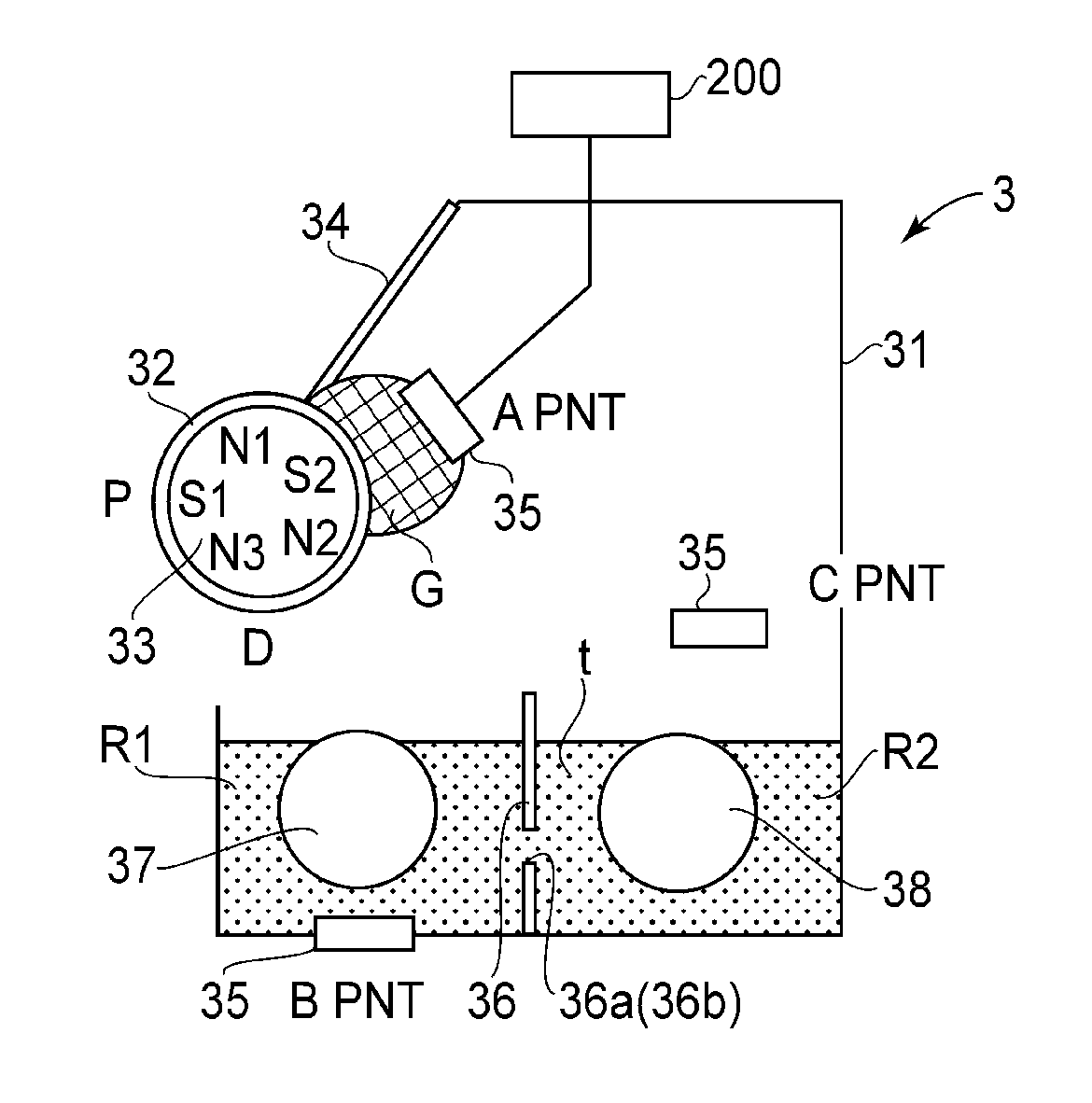
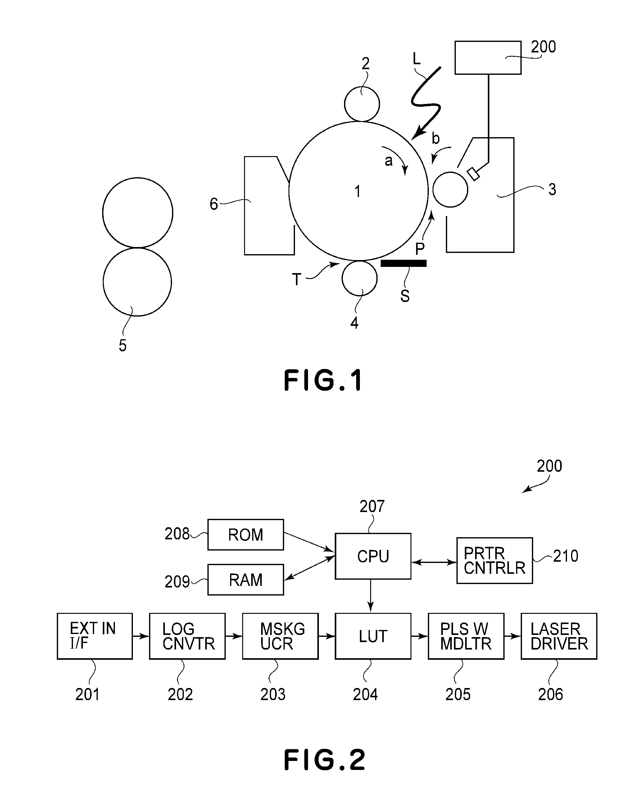
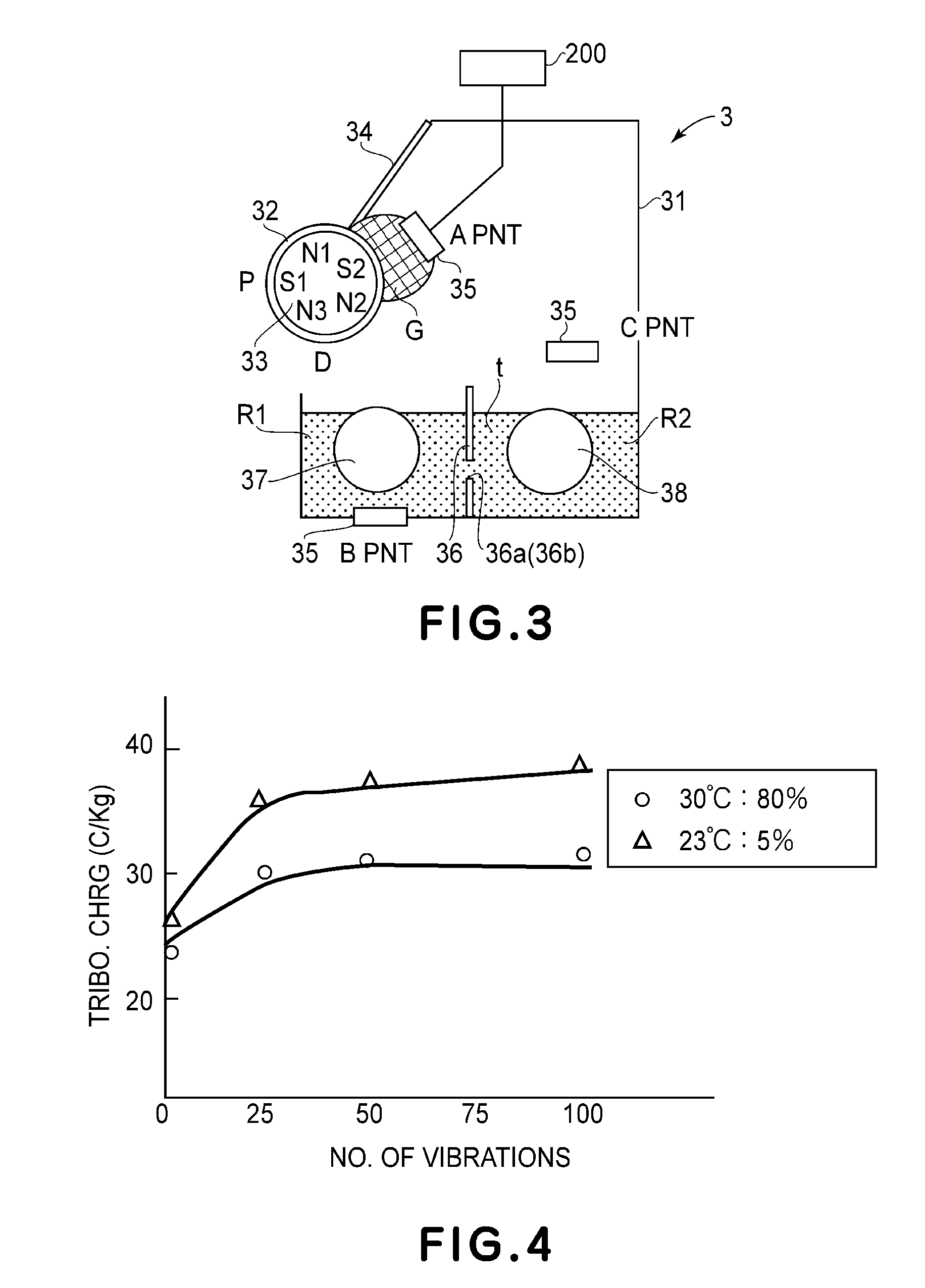
[0035]Next, the first preferred embodiment of the present invention is described. Referring to FIG. 3 which shows the developing apparatus 3 which is an integral part of the image forming apparatus described above, the developing apparatus 3 which develops an electrostatic latent image has a developer container 31, a development sleeve 32 (developer bearing member), a magnet 33 (multipolar magnet), a regulating blade 34 (developer regulating member), and an environment sensor 35 (detecting means).

[0036]Among the abovementioned portions of the developing apparatus 3, the developer container 1 is a container in which developer t, which is two-component developer which is made up of magnetic carrier and nonmagnetic toner, is stored. It has a development chamber R1 and a developer stirring chamber R2, which are separated from each other by a partition wall 36, that is, a developer container partitioning member which is roughly parallel to the rotational axis of the development sleeve 32...

embodiment 2

[0067]Next, referring to FIGS. 1, 3 and 10, the second preferred embodiment of the present invention is described. As mentioned in the description of the first embodiment of the present invention, it was found out that the location in which the environment sensor 35 is to be placed to accurately detect the changes which occurred to the developer due to the changes in the internal ambience of the developing apparatus 3, is desired to be in the developer reservoir G, which is in the adjacencies of the regulating blade 34. The developer reservoir G in the immediate adjacencies of the peripheral surface of the development sleeve 32 (which is one of decisive factors that affects the amount by which toner is given triboelectricity), and retains an ideal amount of developer. Further, the adjacencies of the regulating blade 34 is relatively sensitive to the thermal changes which occur in the adjacencies of the developer container 31. This is why the developer reservoir G, which is in the ad...

embodiment 3

[0070]Next, referring to FIGS. 1, 3, 10 and 11, the third preferred embodiment is described. In the case of this embodiment, the speed at which the developer on the peripheral surface of the development sleeve 32 is conveyed in the adjacencies of the developer reservoir G was studied in detail. More concretely, from the magnetic flux density pattern of the magnet 33, attention was paid to the component of the magnetic force F (vector) from the magnet 33, which is parallel to the line tangential to the peripheral surface of the development sleeve 32 (peripheral surface of image bearing member) at a given point on the peripheral surface of the development sleeve 32.

[0071]That is, of the density B (Br, Bθ) (vector) of the magnetic flux generated by the magnet 33 at a given point on the peripheral surface of the development sleeve 32, Br stands for the component parallel to the normal line to the peripheral surface of the development sleeve 32, that is, the line perpendicular to the per...


PUM


Abstract

A developing apparatus includes a developing container for accommodating a developer; a rotatable developer carrying member, provided in an opening of the developing container, for feeding the developer to a position opposing image bearing member to develop a latent image formed to the image bearing member; a first chamber, provided in the developing container, for supplying the developer to the carrying member; a second chamber, provided adjacent to the first chamber in the developing container, for accommodating the developer; a first feeding member, provided in the first chamber, for feeding the developer in the first chamber; a second feeding member, provided in the second chamber, for feeding the developer in a direction opposite to a feeding direction of the first feeding member; a partition member partitioning between the first chamber and the second chamber; an opening provided in each of opposite ends of the first chamber to form a circulation path between the first chamber and the second chamber; and detecting means, provided opposed to the opening at a position contacting the developer, for detecting a temperature or humidity for controlling an image forming condition.

Description

FIELD OF THE INVENTION AND RELATED ART[0001]The present invention relates to a developing apparatus and an image forming apparatuses equipped with a developing apparatus. In particular, it relates to those apparatuses structured to develop an electrostatic latent image on their image bearing member(s), with the use of dry developer.[0002]A conventional image forming apparatus, such as a printer and a facsimile, is structured to form an electrostatic latent image on its image bearing member, develop the electrostatic latent image into a visible image with its developing apparatus, and then, transfer the visible image onto a sheet of recording medium to yield a copy (print). As the developing apparatus, there have been proposed developing apparatuses which use two-component developer, that is, developer formed by mixing magnetic carrier and nonmagnetic toner in a preset ratio. These developing apparatuses have been known to develop an electrostatic latent image into a visible image th...

Claims


Application Information

Patent Timeline
Patent Type & Authority Applications(United States)
IPC IPC(8): G03G15/00G03G15/08
CPCG03G2215/0822G03G15/0896
Inventor YAMAUCHI, SATORU STEPHEN
Owner CANON KK
Learn More