Linear actuator

Active Publication Date: 2011-07-07
SMC CORP
View PDF16 Cites 5 Cited by
  • Summary
  • Abstract
  • Description
  • Claims
  • Application Information

AI Technical Summary

Benefits of technology

A general object of the present invention is to provide a linear actuator, which is capable of reliably and stably stopping motion of a slide table, and together therewith, of suppressing genera

Problems solved by technology

However, with the conventional technique according to the aforementioned Japanese Laid-Open Patent Publication No. 2008-057679, for example, in the event that the slide table is moved under a condition in which unbalanced lo

Method used


Image

  • Linear actuator
  • Linear actuator
  • Linear actuator

Examples


Example

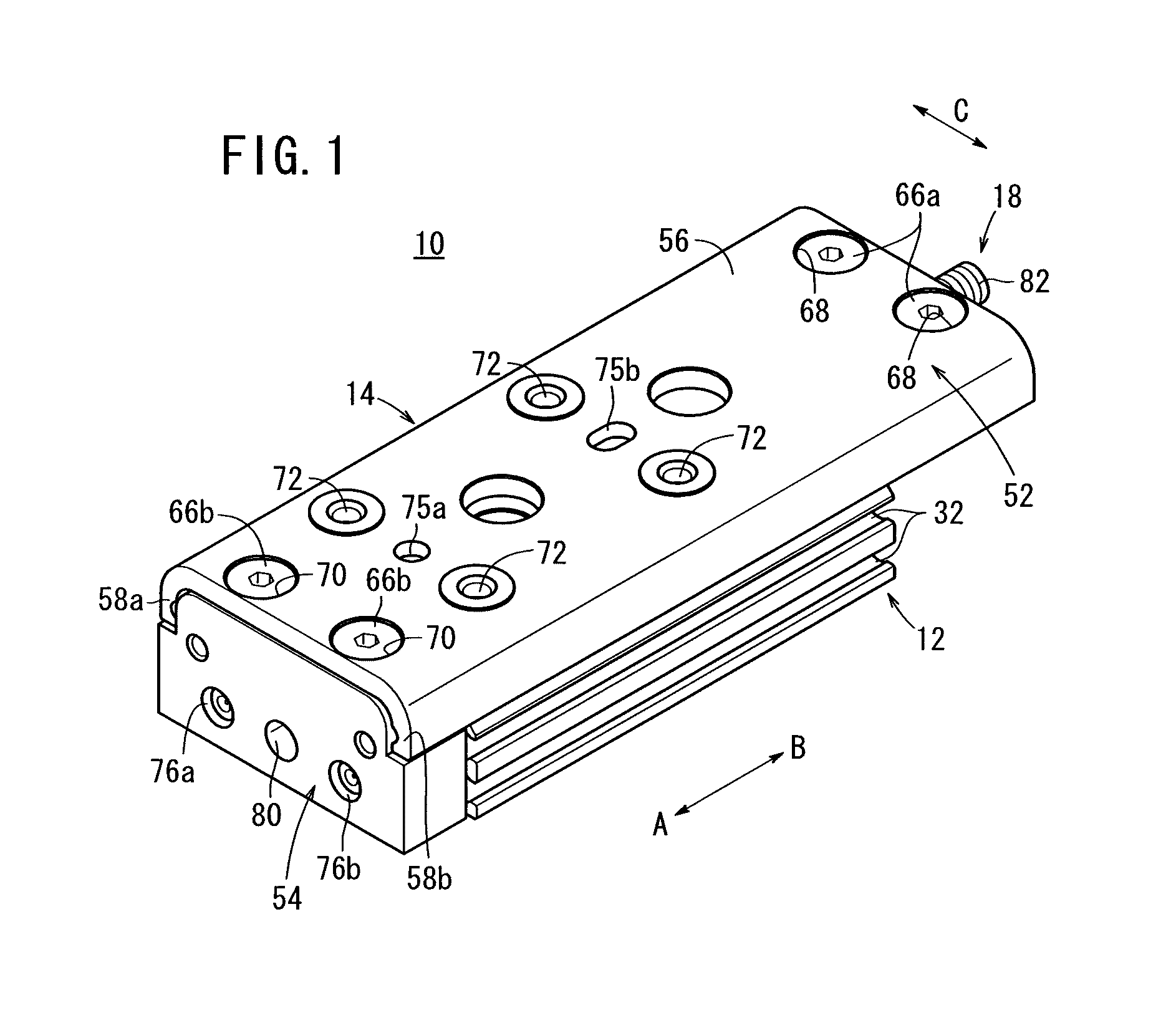
In FIG. 1, reference numeral 10 indicates a linear actuator according to a first embodiment of the present invention.

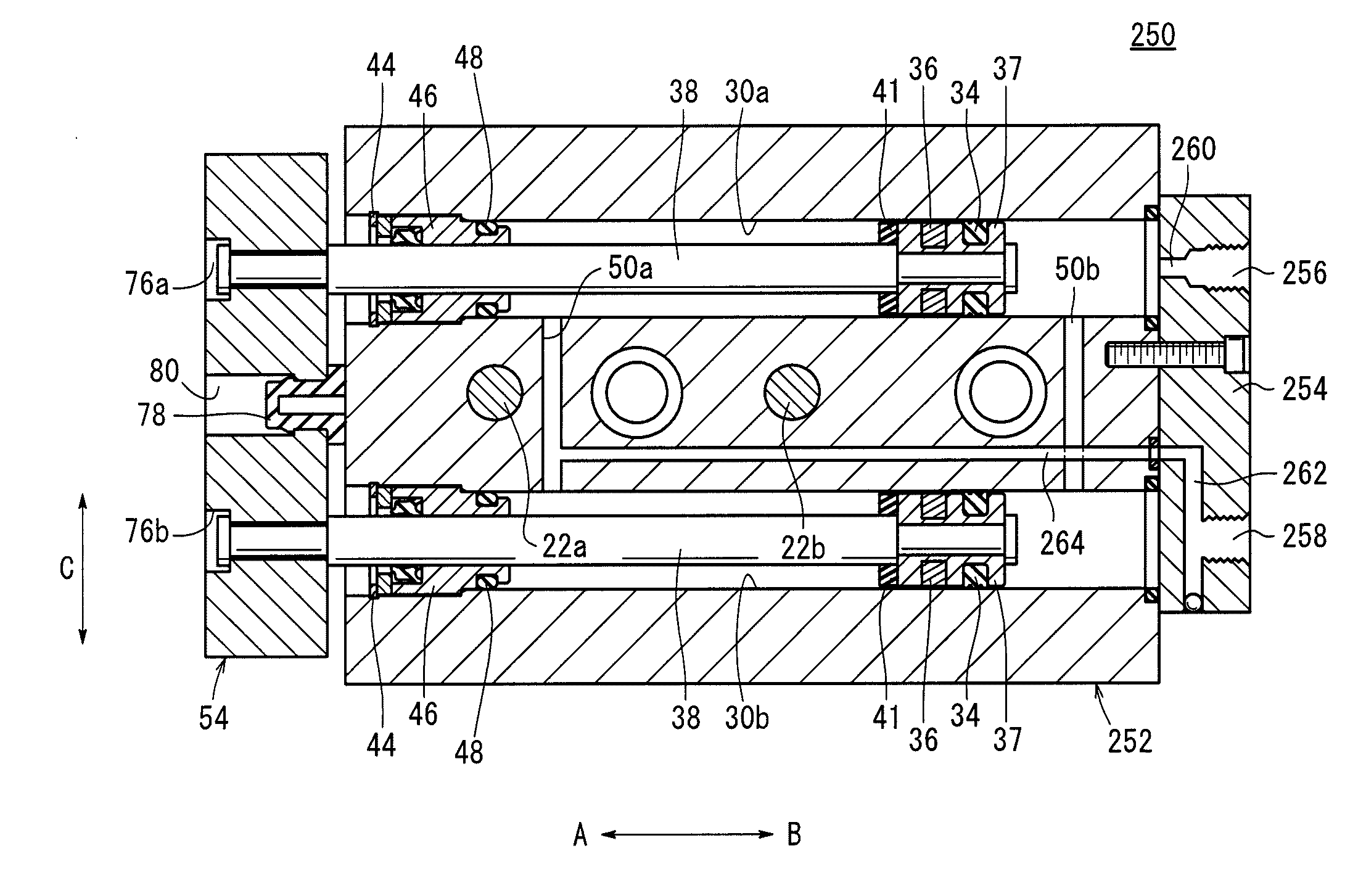
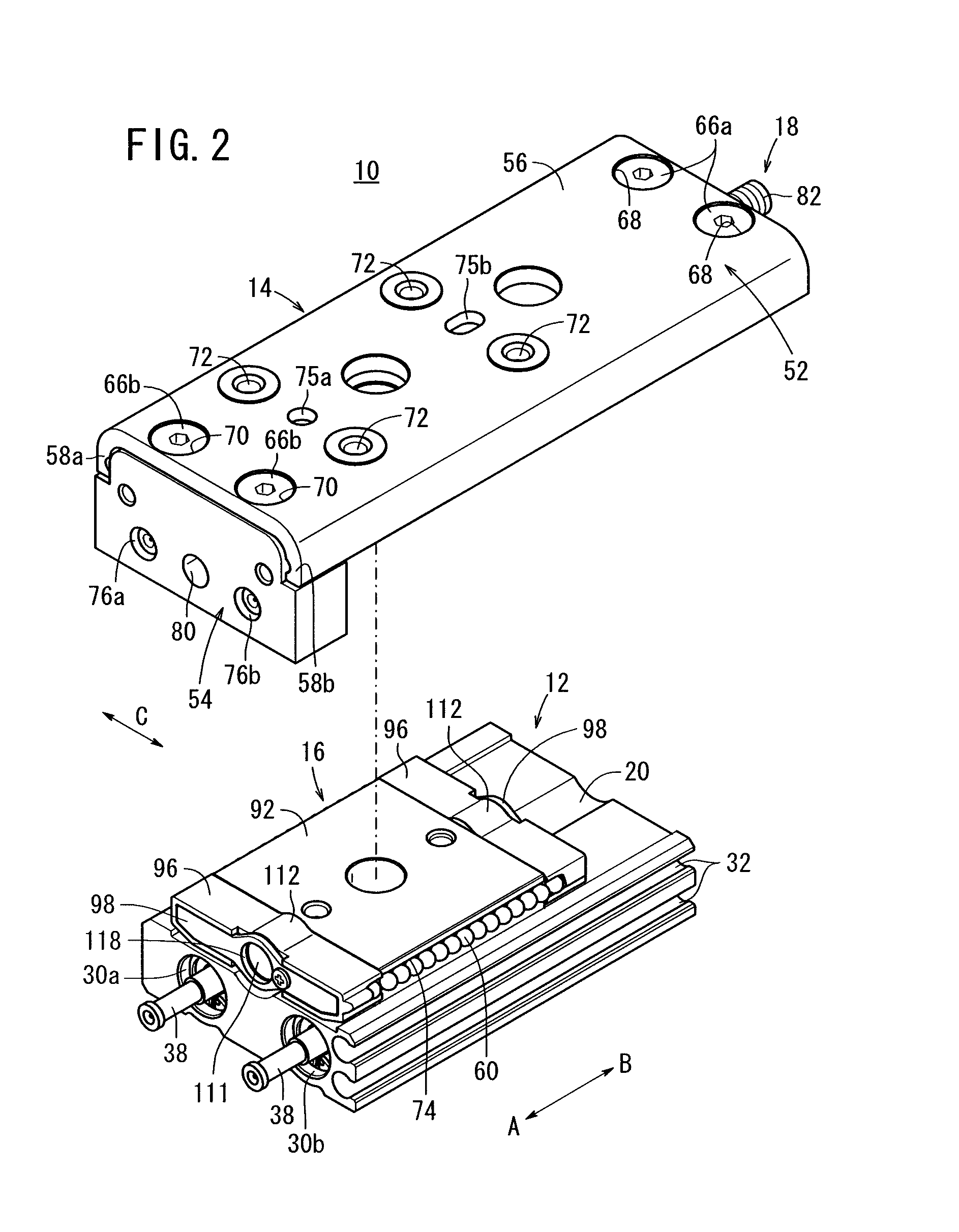
As shown in FIGS. 1 through 10, the linear actuator 10 comprises a cylinder main body 12, a slide table 14 disposed on an upper portion of the cylinder main body 12 and which makes reciprocal motion in a straight line along a longitudinal direction (the direction of arrows A and B), a guide mechanism 16 disposed to intervene between the cylinder main body 12 and the slide table 14, for guiding the slide table 14 in the longitudinal direction (the direction of arrows A and B), and a stopper mechanism 18, which is capable of adjusting a displacement amount of the slide table 14.

The cylinder main body 12 has a rectangular cross section and has a predetermined length along the longitudinal direction (the direction of arrows A and B). A recess 20 having a sunken arcuate shape in cross section is formed roughly in the center on the upper surface of the cylinder main body 12...

Example

Next, a linear actuator 150 according to a second embodiment is shown in FIGS. 11 through 16. Structural elements thereof, which are the same as those of the linear actuator 10 according to the above-described first embodiment, are denoted by the same reference characters, and detailed description of such features is omitted.

The linear actuator 150 according to the second embodiment differs from the linear actuator 10 according to the first embodiment, in that, as shown in FIGS. 11 through 16, at the same time that the first and second ports 26, 28 are formed in one side surface of a cylinder main body 152, another third and fourth ports (fluid inlet / outlet ports) 154, 156 (see FIG. 14) for supplying and discharging the pressure fluid are formed in the other side surface of the cylinder main body 152, and in addition, sensor attachment grooves 158a, 158b (see FIG. 15) are formed respectively on the one side surface and the other side surface of the cylinder main body 152.

Further, th...

Example

Next, a linear actuator 250 according to a third embodiment is shown in FIGS. 20 through 21. Structural elements thereof, which are the same as those of the linear actuators 10, 150 according to the above-described first and second embodiments, are denoted by the same reference characters, and detailed description of such features is omitted.

The linear actuator 250 according to the third embodiment differs from the linear actuator 10, 150 according to the first and second embodiments, in that, instead of providing first and second ports 26, 28 in one side surface and the other side surface of the cylinder main body 12, first and second ports 256, 258 are provided in an end block 254, which is connected to an end of the cylinder main body 252.

The end block 254 is connected to one end of the cylinder main body 252 so as to close and seal the penetrating holes 30a, 30b. The first and second ports 256, 258 are formed in an end surface of the end block 254, separated a given distance in ...


PUM


Abstract

A linear actuator includes a cylinder main body. With respect to the cylinder main body, a slide table is disposed for reciprocal displacement through a guide mechanism, which is disposed on the cylinder main body. A stopper mechanism having a stopper bolt is disposed on one end of the slide table centrally in a widthwise direction perpendicular to the longitudinal direction of the slide table. In addition, when the slide table is displaced along the cylinder main body, an end of the stopper bolt comes into abutment with an end of a cover of the guide mechanism, whereupon the slide table becomes engaged therewith and movement of the slide table is stopped.

Description

BACKGROUND OF THE INVENTION1. Field of the InventionThe present invention relates to a linear actuator in which, by introduction of a pressure fluid from fluid inlet / outlet ports, a slide table is made to move reciprocally along an axial direction of a cylinder main body.2. Description of the Related ArtHeretofore, a linear actuator, for example made up of a fluid pressure cylinder or the like, has been used as a means for transporting workpieces. As disclosed in Japanese Utility Model No. 2586276, the present applicants have proposed a linear actuator, which is capable of transporting a workpiece that is loaded onto a slide table by causing the slide table to move reciprocally in a straight line along a cylinder main body.Further, in Japanese Laid-Open Patent Publication No. 2008-057679, a linear actuator is disclosed equipped with a non-circulating guide mechanism, in which plural steel balls are disposed in a body between a guide rail and a slide table, such that the steel balls ...

Claims


Application Information

Patent Timeline
IPC IPC(8): F15B11/16
CPCF15B15/1404F15B15/24F15B15/1471
Inventor ISHIBASHI, KOICHIROTAKANASHI, SEIJISATO, MOTOHIROMANDOKORO, JIROHARA, KOJISATO, TOSHIO
Owner SMC CORP
Why Eureka
Try Eureka