Composite reeling device

Active Publication Date: 2017-03-09
WU TERA I DAR
View PDF0 Cites 2 Cited by
  • Summary
  • Abstract
  • Description
  • Claims
  • Application Information

AI Technical Summary

Benefits of technology

[0015]Therefore, the composite reeling device has an advantage, that is, a plurality of inner wheel frames define a plurality of spaces for receiving the wires of different types to thereby enhance ease of use. The composite reeling device has some other advantages: the shaft, sleeve, outer wheel frames and inner wheel frames can be removed during a storage process and a transport process so as to be stored and stac

Problems solved by technology

Since there are spaces between each of the outer wheel frames 80 and two adjacent inner wheel frames 90, it is difficult to stack up the conventional reeling devices, th

Method used


Image

  • Composite reeling device
  • Composite reeling device
  • Composite reeling device

Examples


Example

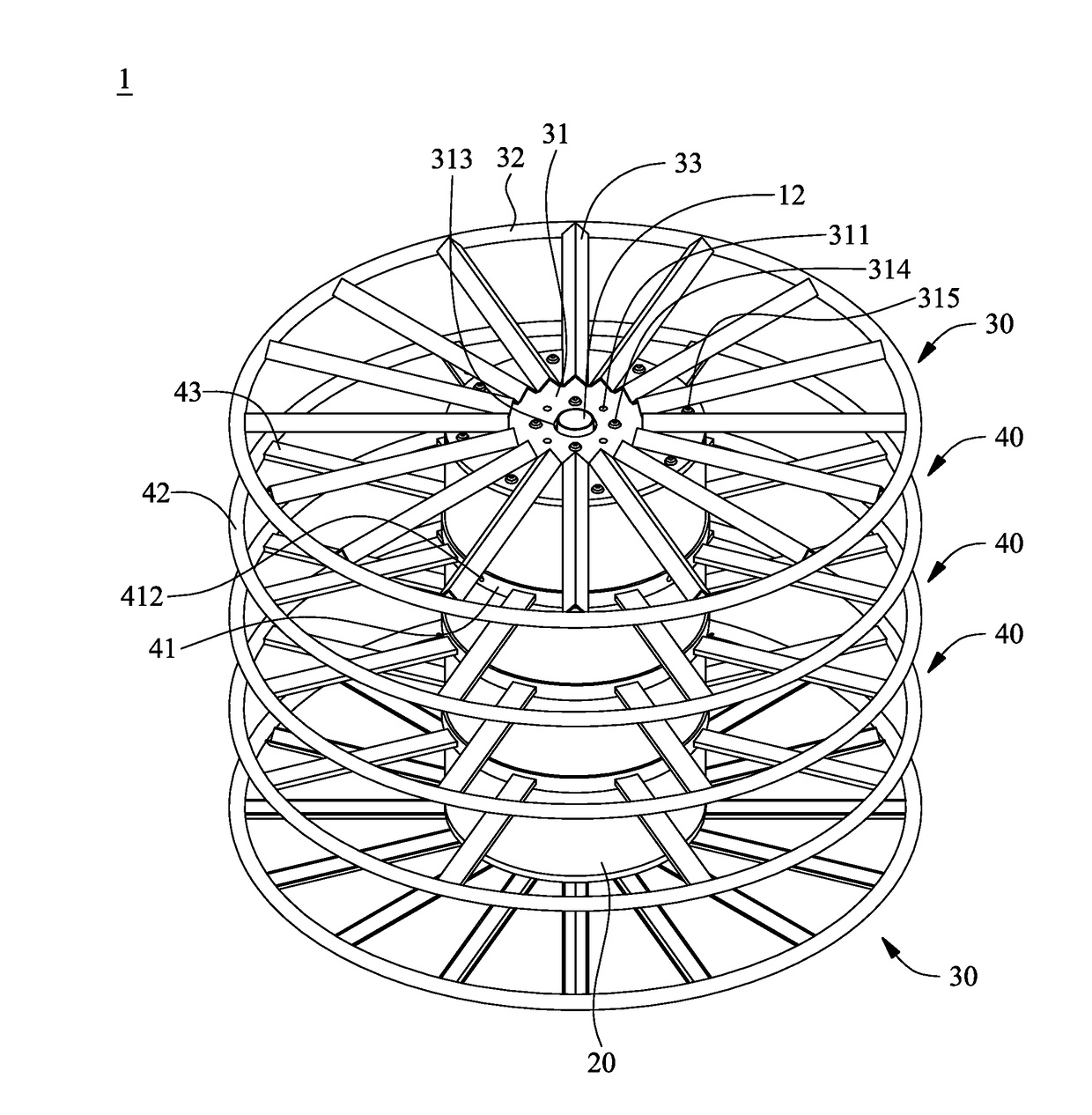
[0024]According to an embodiment of the present invention, a composite reeling device is for use in reeling cables, steel ropes and cords (hereinafter collectively referred to as wires) to facilitate the storage and transport thereof

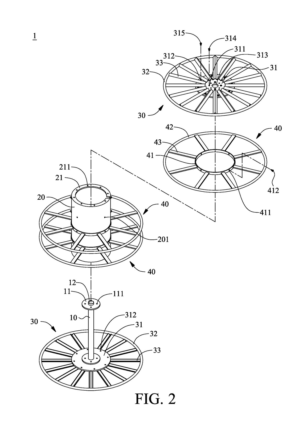
[0025]Referring to FIG. 2, there is shown an exploded view of a composite reeling device 1 according to an embodiment of the present invention. The composite reeling device 1 comprises a shaft 10, a sleeve 20, two outer wheel frames 30 and a plurality of inner wheel frames 40. A fixing end plate 11 is disposed at each of the two opposing ends of the shaft 10. The sleeve 20 is fitted around the shaft 10. A fixing flange 21 is disposed at each of the two opposing ends of the sleeve 20. The fixing flanges 21 correspond in position to the fixing end plates 11, respectively. The two outer wheel frames 30 are disposed at the two ends of the sleeve 20, respectively. The outer wheel frames 30 are removably coupled to the fixing flanges 21 and the fixing end plat...


PUM


Abstract

A composite reeling device for winding up and letting out cables, steel ropes and cords includes a shaft, a sleeve, two outer wheel frames and a plurality of inner wheel frames. Two fixing end plates are disposed at two opposing ends of the shaft, respectively. The sleeve is fitted around the shaft. Fixing flanges are disposed at two opposing ends of the sleeve, respectively. The fixing flanges correspond in position to the fixing end plates, respectively. The outer wheel frames are disposed at the two ends of the sleeve, respectively, and removably coupled to the fixing flanges and the fixing end plates, respectively. The inner wheel frames each have a belt, a supporting ring and spokes. The spokes each have two ends connected to corresponding ones of the belts and the supporting rings. The belts are fitted around the sleeve.

Description

FIELD OF THE INVENTION[0001]The present invention relates to composite reeling devices and more particularly to a composite reeling device for reeling cables, steel ropes, cords, etc.BACKGROUND OF THE INVENTION[0002]A reeling device is for use in reeling cables, steel ropes, and cords (hereinafter collectively referred to as wires) to facilitate the storage and transport thereof Referring to FIG. 1, there is shown a schematic view of a conventional reeling device.[0003]Referring to FIG. 1, the conventional reeling device comprises an internal shaft 60, a drum 70, two outer wheel frames 80 and a plurality of inner wheel frames 90. The internal shaft 60 has two opposing ends each provided with an end plate 61. The internal shaft 60 is penetratingly disposed in the drum 70. The two outer wheel frames 80 are disposed at the two opposing ends of the drum 70, respectively. The outer wheel frames 80 each have a plurality of connection bars 81 and an outer ring 84. The connection bars 81 ha...

Claims


Application Information

Patent Timeline
IPC IPC(8): B65H75/14B65H75/22
CPCB65H75/22B65H75/146B65H75/2227B65H75/2263
Inventor WU, TERA I-DAR
Owner WU TERA I DAR
Why Eureka
Try Eureka