Transfer device

a transfer device and transfer technology, applied in the field of tandemtype transfer devices, can solve the problems of the highest possibility of transfer failure, and achieve the effects of reducing the occurrence of picture quality deficiencies, and reducing the number of image bearing parts

Active Publication Date: 2011-07-07
SHARP KK
View PDF10 Cites 7 Cited by
  • Summary
  • Abstract
  • Description
  • Claims
  • Application Information

AI Technical Summary

Benefits of technology

[0011]Thereby, assuming that a direction of rotating shafts of the plurality of image bearing members is arranged in a horizontal direction, even if the endless belt is stretched obliquely onto the image bearing member disposed on the most upstream side from an upper direction toward a lower direction, because the image bearing member disposed on the most upstream side and the opposed transfer member have the common zone of contact in the direction of movement of the endless belt, a nip pressure between the image bearing member disposed on the most upstream side and the endless belt can be rendered stable; thus the transfer failure can be prevented. Besides, since the other image bearing members and the opposed respective transfer members do not have any common zone of contact in the direction of movement of the endless belt, nip pressures between the other image bearing members and the endless belt can be lowered; thus the occurrence of missing characters due to toner aggregation or the like can be prevented. As a consequence, decreasing the occurrence of deficiencies in picture quality can be realized while downsizing the device.
[0015]Consequently, the occurrence of deficiencies in picture quality can be reduced in color printing. Additionally, in monochromatic printing, by disposing the image bearing member used therefor on the most downstream side, distance in horizontal direction can be separated most from either the drive roller or the compliance roller between both of which the endless belt is stretched, whichever is disposed on the upstream side; thus, an entry angle of the endless belt to the image bearing member can be decreased (lowered) most. Thereby, the nip pressure between the image bearing member and the endless belt is rendered stable, so that missing characters due to toner transfer void does not occur; hence the transfer failure does not occur.
[0016]With the transfer device according to the present invention, decreasing the occurrence of deficiencies in picture quality while downsizing the device can be realized.

Problems solved by technology

Since the image bearing member disposed on the most upstream side has the zone of contact that is in common with the opposed transfer member in the direction of movement of the endless belt, the nip pressure thereof is incapable of being lowered; thereby missing characters due to toner aggregation, etc. occurs; and it is where the possibility that the transfer failure occurs is the highest.

Method used


Image

  • Transfer device
  • Transfer device
  • Transfer device

Examples


Embodiment Construction

[0027]An image forming apparatus comprising a transfer device according to an embodiment of the present invention is explained below referring to the drawings.

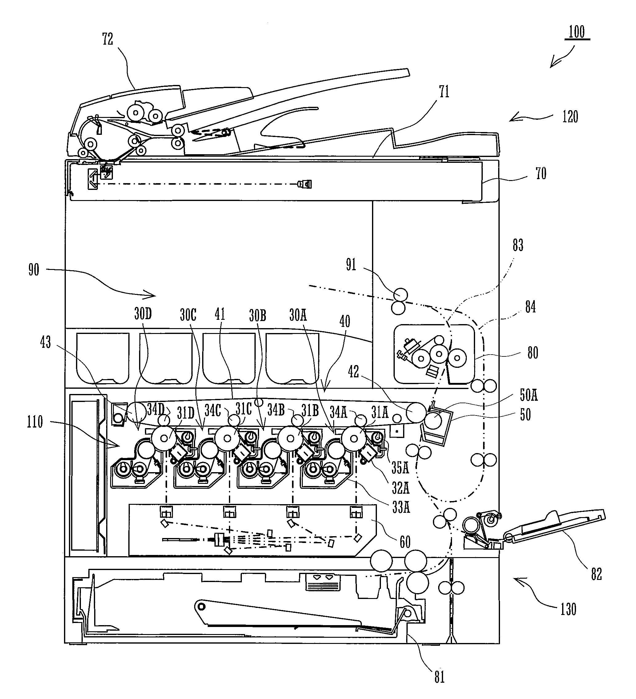
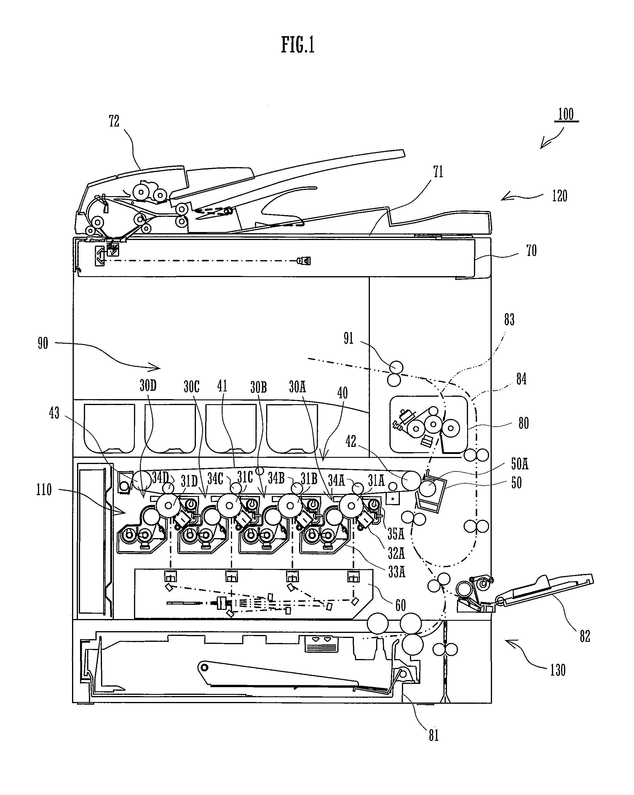
[0028]FIG. 1 is a schematic front sectional view of an image forming apparatus comprising a transfer device according to the present invention. The image forming apparatus 100 forms a multicolored or a monochromatic image onto a predetermined sheet of paper (recording medium) based on image data that have been read from a document. For this purpose, the image forming apparatus 100 is equipped with an image reading device 120 in the upper part of its main body, and is provided with an image forming section 110 (corresponding to a transfer device of the present invention) and a paper supply section 130 inside the main body.

[0029]The image reading device 120 includes a scanner unit 70, a document table 71, and an automated document feeder 72. The scanner unit 70 reads data for printing from an image plane of the document placed o...


PUM


Abstract

A transfer device of the invention includes an endless belt forming a loop-shaped path of movement passing over between a drive roller and an idle roller, a plurality of image bearing members disposed at positions along a direction of movement of the endless belt, and a plurality of transfer members disposed at positions on respective downstream sides of the plurality of image bearing members so as to oppose a plurality of respective image bearing members across the endless belt. The image bearing member disposed on the most upstream side in the direction of movement of the endless belt has a zone of contact in common with the opposed transfer member in the direction of movement of the endless belt. Whereas the other image bearing members do not have any zone of contact in common with the opposing respective transfer members in the direction of movement of the endless belt.

Description

CROSS REFERENCE[0001]This Nonprovisional application claims priority under 35 U.S.C. §119(a) on Patent Application No. 2010-001916 filed in Japan on Jan. 7, 2010 the entire contents of which are hereby incorporated by reference.BACKGROUND OF THE INVENTION[0002]The present invention relates to a tandem-type transfer device that is provided with a plurality of photoreceptor drums for respective hues and transcribes toner images formed on the respective photoreceptor drums to an intermediate transfer belt.[0003]In conventional tandem systems, transfer of the toner images on the respective photoreceptor drums to the intermediate transfer belt has been carried out by applying a transfer bias to each of the photoreceptor drums (for instance, refer to Japanese Patent Unexamined Publication No. 2005-234229 bulletin).[0004]In conventional image forming apparatus, the photoreceptor drums and the plurality of intermediate transfer rollers have been disposed at such positions that contact is ma...

Claims


Application Information

Patent Timeline
Patent Type & Authority Applications(United States)
IPC IPC(8): G03G15/01
CPCG03G15/0131G03G15/0194G03G15/0136G03G2215/0132
Inventor TAKIGUCHI, TOSHIKI
Owner SHARP KK
Why Eureka
Try Eureka