
Modular voltage sensor

a voltage sensor and module technology, applied in the field of voltage sensors, can solve the problems of sensitivity to the capacitance between the primary and secondary windings of the current transformer, the accuracy of the measurement string and the efficacy of the shielding method are questionable, and the above-referenced prior art has one or more limitations in measurement performance, size, safety and cost, etc., to achieve wide frequency response, high accuracy, and low weight

Inactive Publication Date: 2006-10-31
FIELDMETRICS
View PDF17 Cites 16 Cited by
  • Summary
  • Abstract
  • Description
  • Claims
  • Application Information

AI Technical Summary

Benefits of technology

The modular design achieves high accuracy (0.1% amplitude and 0.03 degrees phase angle) with wide frequency response (1 Hz to 1 MHz), insensitivity to external perturbations, and robustness against high voltage transients, while reducing weight and maintenance needs, and meeting stringent power distribution and transmission standards.

Problems solved by technology

The accuracy (both magnitude and phase angle) of the measurement string and the efficacy of the shielding method are questionable, since the AC impedance of the resistors must be high (>10 Megohms) to avoid excessive heating during operation.
The method suffers from sensitivity to the capacitance between the primary and secondary windings of the current transformer, which varies with temperature and time.
The above-referenced prior art has one or more limitations in measurement performance, size, safety and cost.
Inductive voltage transformers and capacitive voltage transformers use insulating polymeric solids, insulating oil or sulfur hexafluoride gas for insulation, resulting in a heavy or expensive device.
The high resistance, when combined with the distributed capacitance of the structure, causes the high frequency response of the device to be limited.
Capacitive voltage dividers can fail catastrophically if the elements comprising the divider fail in the short circuit condition.
Large voltage transients with respect to time, or dV / dt, can cause a pure capacitive divider to fail because of the large displacement current that flows through the device.
Line integral optical voltage sensors are physically small to keep costs affordable, and as a result they require insulating fluids and expensive housings to support the large electric fields near the sensor element.
For example, water vapor condensing on the electric field sensor will cause large errors in measurement.
An expensive and continuously monitored housing is required to maintain the dry, insulating environment required for this approach.

Method used


Image

  • Modular voltage sensor
  • Modular voltage sensor
  • Modular voltage sensor

Examples


Embodiment Construction

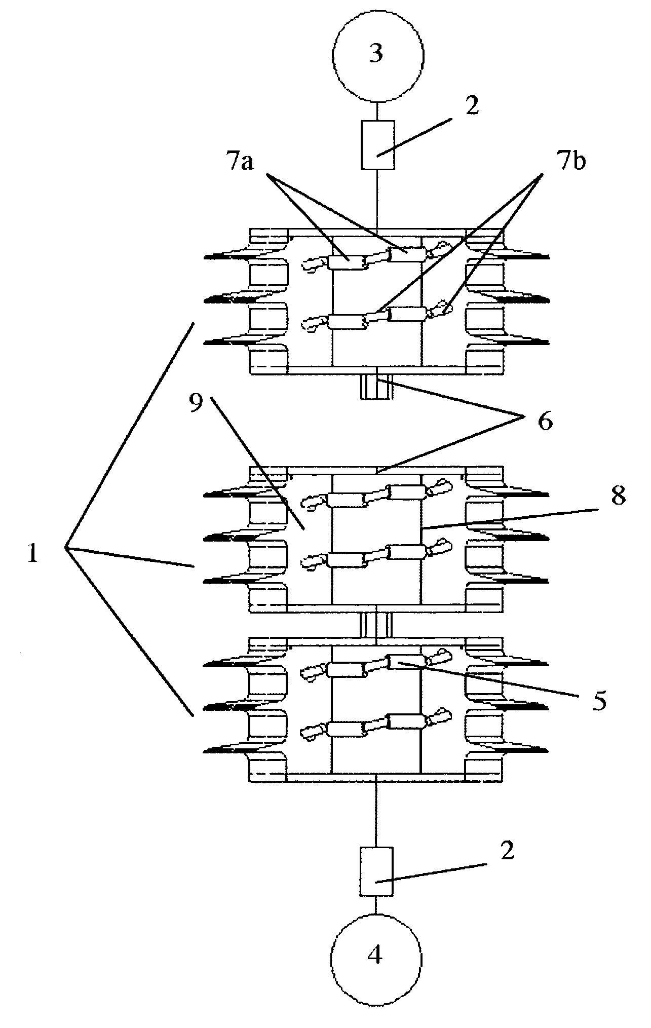
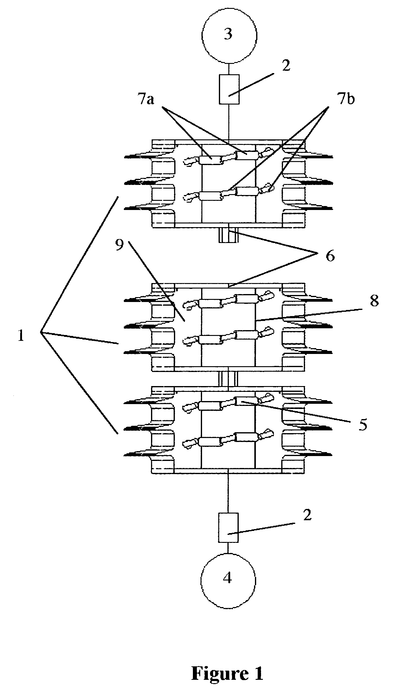
[0022]A modular voltage sensor is described (shown in FIG. 1) having a modular high voltage arm in series with one or more low voltage impedance elements 2 between two conductors 3 and 4 at different electrical potentials. The high voltage arm is comprised of one or more modular sections 1 stacked in series as needed to allow operation at any voltage level. Each modular section has mounting hardware 6 for making mechanical and electrical connections to adjacent sections in the stack. An output signal is provided by measuring the voltage across a low voltage impedance element 2 at one or both ends of the modular high voltage arm. Each modular section of the divider structure is contained within an insulating housing made from porcelain or polymer with weather sheds 10 on the exterior surface. Each modular section 1 of the high voltage arm is comprised of a plurality of alternating impedances 7a and 7b connected in series to form one or more impedance strings 5. Impedance 7a is a capa...


PUM


Abstract

A voltage sensor is described that consists of a plurality of identical series-connected sections, where each section is comprised of an arrangement of impedance elements. The sensor is optimized to provide an output ratio that is substantially immune to changes in voltage, temperature variations or aging. The voltage sensor can be scaled to various voltage levels by varying the number of series-connected sections.

Description

CROSS REFERENCE TO PRIOR APPLICATION[0001]This application claims the priority of U.S. Provisional Application Ser. No. 60 / 521,902 filed Jul. 19, 2004 and entitled “MODULAR VOLTAGE SENSOR”, the subject matter of which is incorporated herein by reference.FEDERAL GOVERNMENT STATEMENT[0002]This invention was made with Government support under contract NBCHC040109 awarded by the Department of Homeland Security. The Government has certain rights to this invention.FIELD OF THE INVENTION[0003]The present invention relates to a voltage sensor for measuring voltage such as the voltage of a high-voltage power transmission line.DESCRIPTION OF THE PRIOR ART[0004]A variety of high-voltage measurement techniques are known in the art, including voltage transformers, capacitive voltage transformers, resistive voltage dividers, capacitive voltage dividers, mixed resistive-capacitive voltage dividers, electric field point sensors, line integral optical voltage sensors and distributed electric field p...

Claims


Application Information

Patent Timeline
Patent Type & Authority Patents(United States)
IPC IPC(8): G01R1/20G01R19/14G01R27/26G01R31/02
CPCG01R15/06
Inventor YAKYMYSHYN, CHRISTOPHER PAULBRUBAKER, MICHAEL ALLENYAKYMYSHYN, PAMELA JANE
Owner FIELDMETRICS
Learn More