Non-contact phase-difference type torque sensor

A torque sensor, non-contact technology, applied in the field of sensors, can solve the problems of reduced sensor accuracy, shortened service life, high installation requirements, etc., and achieve the effects of long service life, simple structure and low cost

Inactive Publication Date: 2010-12-08
TONGJI UNIV
View PDF8 Cites 7 Cited by
  • Summary
  • Abstract
  • Description
  • Claims
  • Application Information

AI Technical Summary

Problems solved by technology

Existing EPS torque sensors can be divided into two categories: contact type and non-contact type. Contact type torque sensors such as metal resistance strain gauges use a set of strain gauges as sensitive elements, and the strain gauges are pasted in the form of a bridge circuit. On the torque transmission shaft, but when the strain gauge is used in the slewing system, a collector ring device for connecting the strain gauge is required. Due to the existence of mechanical contact, mechanical wear is easy to occur, and the accuracy of the sensor will decrease with use, and the service life will also decrease. Will shorten, need frequent maintenance and replacement, increase cost
The non-contact torque sensor can overcome the above shortcomings. The non-contact torque sensor can be divided into two categories, one is photoelectric. The photoelectric torque sensor has strict requirements on the working environment and high installation requirements. Poor shock resistance and expensive

Method used


Image

  • Non-contact phase-difference type torque sensor
  • Non-contact phase-difference type torque sensor
  • Non-contact phase-difference type torque sensor

Examples


Embodiment Construction

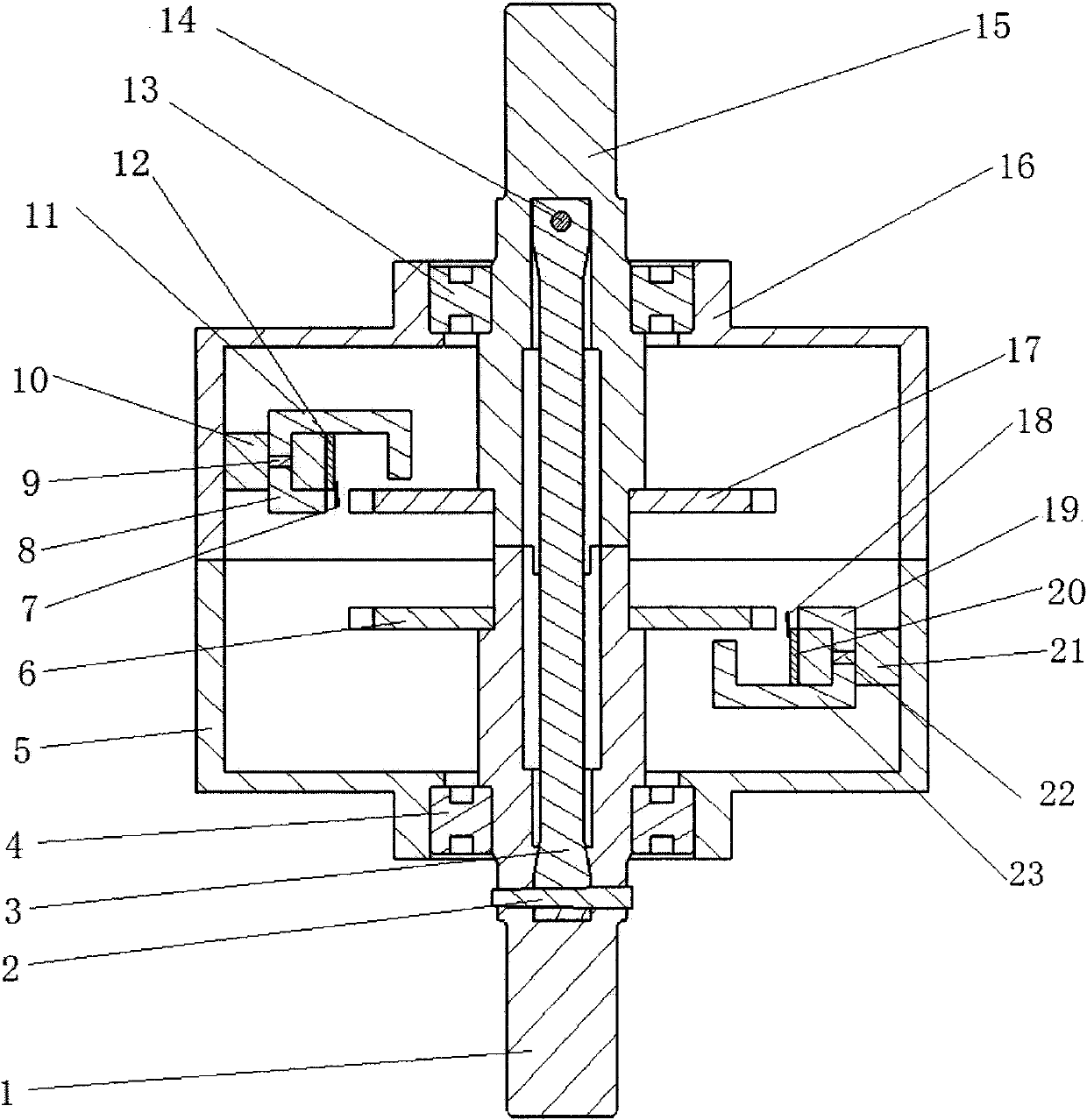
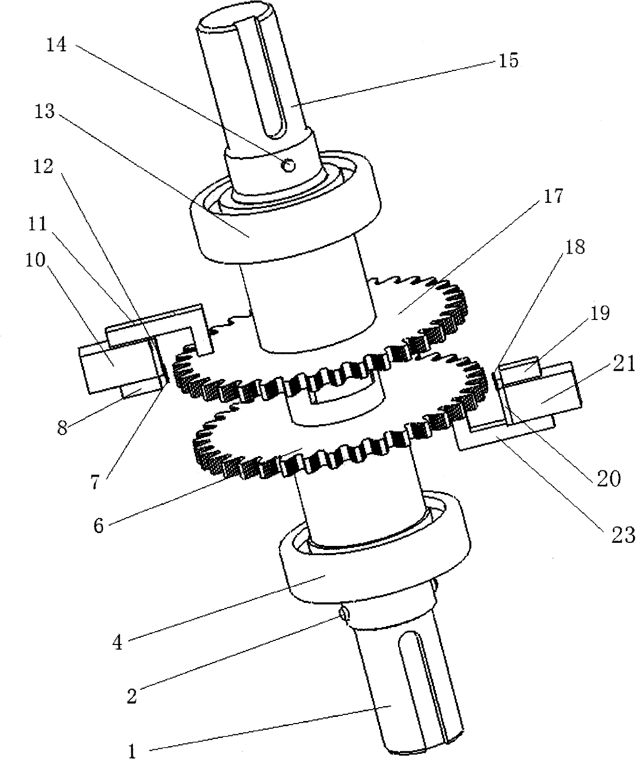
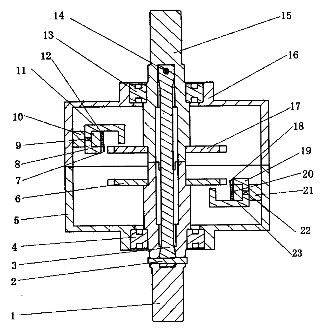
[0030] The present invention will be further described below in conjunction with the embodiments shown in the accompanying drawings.

[0031] The present invention is a non-contact phase difference torque sensor, which includes: input sleeve 15, output sleeve 1, torsion bar 3, first pin 2, second pin 14, first bearing 4, second bearing 13, first A sensor housing 5, a second sensor housing 16, a first circuit board 12, a second circuit board 20, a first magnetic circuit support 10, a second magnetic circuit support 21, a first Hall sensor 7, a second Hall sensor Sensor 18, the first involute gear 6, the second involute gear 17, the first magnetic circuit assembly, and the second magnetic circuit assembly, wherein: one end of the input sleeve 15 is connected with the steering wheel through a key, and the input sleeve 15 passes through The spline is connected to one end of the torsion bar 3, and the other end of the torsion bar 3 is connected to the output sleeve 1 through a spli...


PUM


Abstract

The invention relates to a non-contact phase-difference type torque sensor which comprises an input sleeve, an output sleeve, a Hall sensor, a first involute gear and a second involute gear, wherein the input sleeve is connected with the output sleeve through a torsion bar, a hub bore of the first involute gear is in interference fit with the output sleeve, a hub bore of the second involute gear is in interference fit with the input sleeve, third sections of shaft segments of the input sleeve and the output sleeve are respectively matched with an inner ring of a corresponding bearing, an outer ring of the bearing is respectively matched with two groups of sensor shells which are arranged at two sides of the torsion bar, a magnetic circuit support is respectively fixed on the inner surface of each sensor shell, a magnetic circuit assembly and a circuit board are fixed on each magnetic circuit support, the Hall sensor is welded on the circuit board, and a detection surface of the Hall sensor is arranged in an air gap where the end surface of magnetic-conducting soft iron a just faces to a top addendum circle of the involute gear. The invention has the advantages of simple structure, accurate test, good stability, comparatively lower cost, and the like.

Description

technical field [0001] The invention relates to a sensor, in particular to a non-contact phase difference torque sensor using a Hall sensor. Background technique [0002] The torque sensor is one of the most important components of the electric power steering system (EPS) of an automobile. It is the core component of the electric power steering gear and integrates electromechanical technology. Existing EPS torque sensors can be divided into two categories: contact type and non-contact type. Contact type torque sensors such as metal resistance strain gauges use a set of strain gauges as sensitive elements, and the strain gauges are pasted in the form of a bridge circuit. On the torque transmission shaft, but when the strain gauge is used in the slewing system, a collector ring device for connecting the strain gauge is required. Due to the existence of mechanical contact, mechanical wear is easy to occur, and the accuracy of the sensor will decrease with use, and the service l...

Claims


Application Information

Patent Timeline
Patent Type & Authority Applications(China)
IPC IPC(8): G01L3/00
Inventor 周爱国刘畅陈光明
Owner TONGJI UNIV
Why Eureka
Try Eureka