Imaging apparatus

a technology of imaging apparatus and half mirror, which is applied in the field of imaging apparatus, can solve problems such as difficult fast focus detection, and achieve the effect of reducing the amount of light reflected at the half mirror

Inactive Publication Date: 2011-07-07
SONY CORP
View PDF2 Cites 16 Cited by
  • Summary
  • Abstract
  • Description
  • Claims
  • Application Information

AI Technical Summary

Benefits of technology

[0009]According to an embodiment of the present invention, the wavelength of a transmission peak in the spectral transmission characteristic of a half mirror, which splits light from a subject having passed through a photographic optical system into transmitted light and reflected light, matches the wavelength of a sensitivity peak in the spectral sensitivity characteristic of a first light receiving sensor that receives the transmitted light. As a result, a deficiency in the amount of light reflected at the half mirror can be reduced.

Problems solved by technology

This often results in situations where the amount of reflected light is deficient for a dark subject, making fast focus detection difficult.

Method used


Image

  • Imaging apparatus
  • Imaging apparatus
  • Imaging apparatus

Examples


first embodiment

[Configuration of Main Part of Imaging Apparatus]

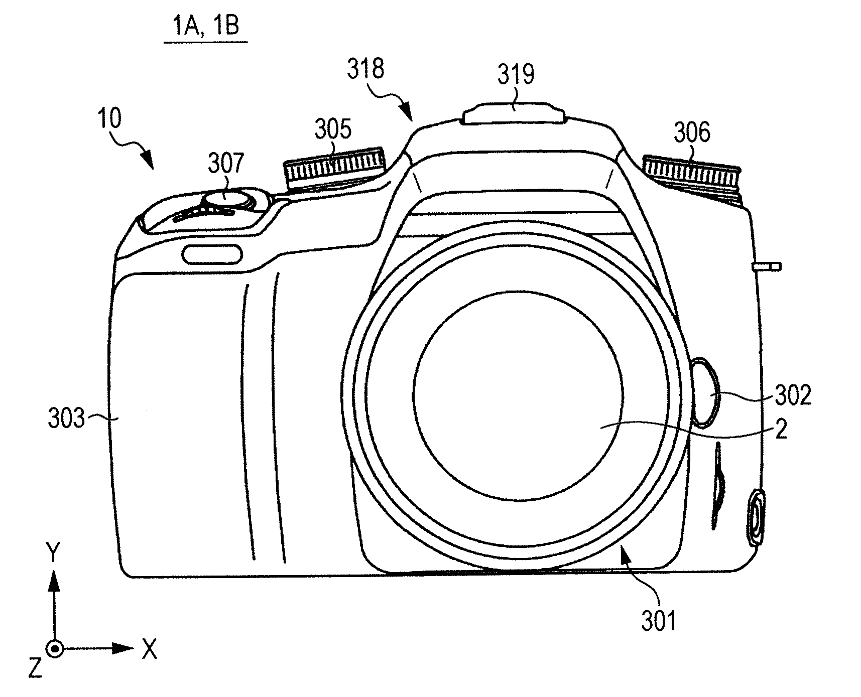
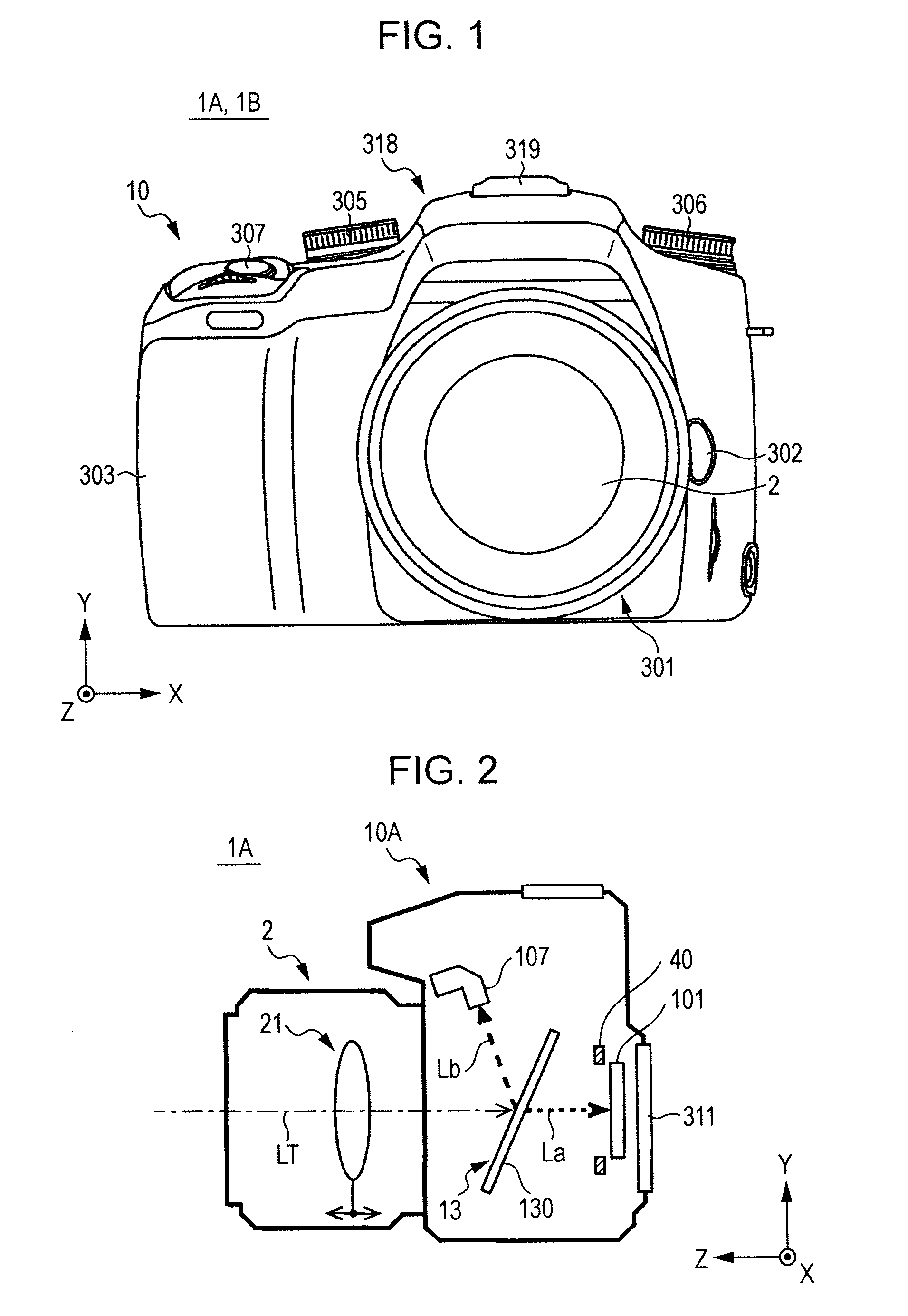
[0027]FIG. 1 is a front view showing the exterior configuration of an imaging apparatus 1A according to a first embodiment of the present invention.

[0028]The imaging apparatus 1A is configured as a digital still camera, and includes a camera body 10A, and an interchangeable lens 2 serving as a taking lens that can be attached to and detached from the camera body 10A.

[0029]In FIG. 1, on the front side of the camera body 10A, there are provided a mount section 301 at substantially the center of the front side to which the interchangeable lens 2 is mounted, a lens change button 302 placed to the right of the mount section 301, and a grip section 303 for allowing the imaging apparatus 1A to be gripped. In addition, the camera body 10A has a mode setting dial 305 placed at the left top of the front side, a control-value setting dial 306 placed at the right top of the front side, and a shutter button 307 placed on the top face of the grip s...

second embodiment

[Configuration of Imaging Apparatus]

[0088]FIG. 14 is a vertical sectional view of an imaging apparatus 1B according to a second embodiment of the present invention. FIG. 15 is a block diagram showing the electrical configuration of the imaging apparatus 1B.

[0089]Although the imaging apparatus 1B according to the second embodiment has the same exterior configuration as the imaging apparatus 1A according to the first embodiment shown in FIG. 1, the imaging apparatus 1B differs in that instead of the phase difference AF module 107 according to the first embodiment, an imaging device (image sensor) 102 is installed inside a camera body 10B as a light receiving sensor that receives the reflected light Lb from the half mirror 130.

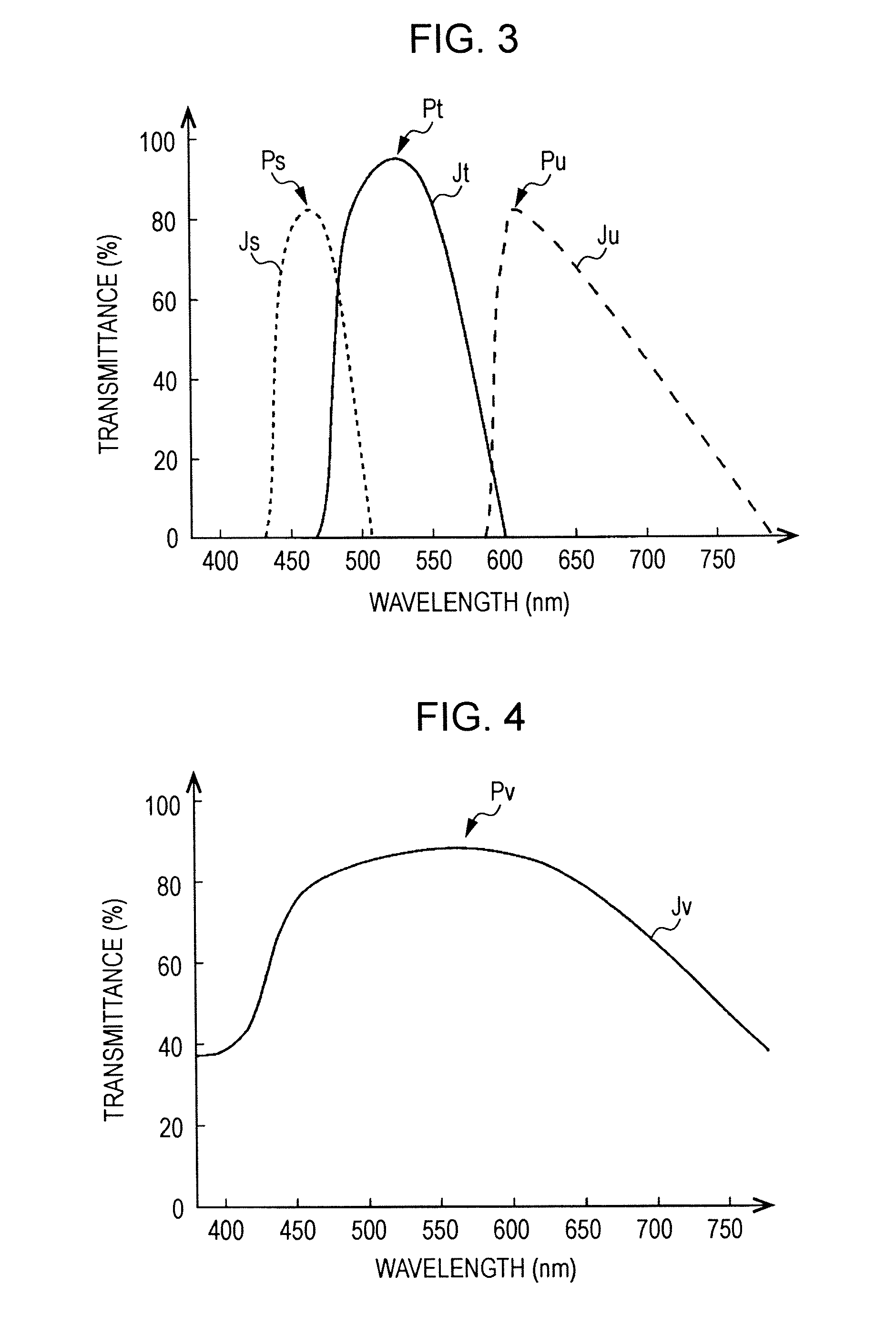
[0090]Although the imaging device 102 has a configuration equivalent to that of the imaging device 101, as described below, the imaging device 102 differs in its spectral sensitivity characteristics with respect to color filters.

[Spectral Sensitivity Characterist...


PUM


Abstract

An imaging apparatus includes a half mirror that splits light from a subject having passed through a photographic optical system into transmitted light and reflected light, a first light receiving sensor that receives the transmitted light, the first light receiving sensor having a spectral sensitivity characteristic with a sensitivity peak at a specific wavelength of light, and a second light receiving sensor that receives the reflected light. The wavelength of a transmission peak in the spectral transmission characteristic of the half mirror matches the wavelength of the sensitivity peak of the first light receiving sensor.

Description

BACKGROUND OF THE INVENTION[0001]1. Field of the Invention[0002]The present invention relates to an imaging apparatus including a half mirror that splits light from a subject having passed through a photographic optical system into transmitted light and reflected light.[0003]2. Description of the Related Art[0004]Among imaging apparatuses such as digital still cameras, there has been proposed an imaging apparatus which has a half mirror (semi-transparent mirror) provided on the optical path of light from a subject having passed through a taking lens, so that light transmitted through the half mirror is made incident on an imaging device to enable acquisition of an image of the subject, and reflected light is made incident on a range sensor (AF sensor) or a metering sensor (AE sensor) to enable focus detection or the like for the subject (see, for example, Japanese Unexamined Patent Application Publication No. 2008-52246).[0005]Such a half mirror is so designed / fabricated that the ra...

Claims


Application Information

Patent Timeline
Patent Type & Authority Applications(United States)
IPC IPC(8): H04N5/335H04N5/225
CPCG02B27/141G02B27/142G03B11/00H04N9/045G03B19/12H04N5/2254G03B13/36H04N23/672H04N23/632H04N25/134
Inventor KATSUDA, YASUTOSHI
Owner SONY CORP
Why Eureka
Try Eureka