Projector that projects an image signal on a display surface

a projector and image technology, applied in the field of projectors, can solve the problems of difficult realization, difficult monitoring structure, and inability to enjoy video entertainment, and achieve the effects of reducing deficiencies, accurate detection of optical elements, and effective use of spa

Active Publication Date: 2011-12-06
SEIKO EPSON CORP
View PDF15 Cites 15 Cited by
  • Summary
  • Abstract
  • Description
  • Claims
  • Application Information

AI Technical Summary

Benefits of technology

An advantage of some aspect of the invention is to provide a projector that makes it possible to realize both reduction in deficiencies that are likely to be caused by light and comfortable video entertainment and has a simple configuration.
It is preferable that the light source device emits a laser beam. This makes it possible to perform image display using the laser beam. According to the invention, it is possible to configure the laser beam source conforming to standards required for apparatuses that use laser beam sources.

Problems solved by technology

When the unnecessary stop of the output is frequency performed, comfortable video entertainment is hindered.
If it is necessary to perform an arithmetic operation using an extremely large number of parameters in order to highly accurately detect that a person enters the monitoring region, the structure for monitoring is complicated.
In this way, the technique in the past causes a problem that it is difficult to realize, with a simple configuration, both reduction in deficiencies that are likely to be caused by light and comfortable video entertainment.

Method used


Image

  • Projector that projects an image signal on a display surface
  • Projector that projects an image signal on a display surface
  • Projector that projects an image signal on a display surface

Examples


first embodiment

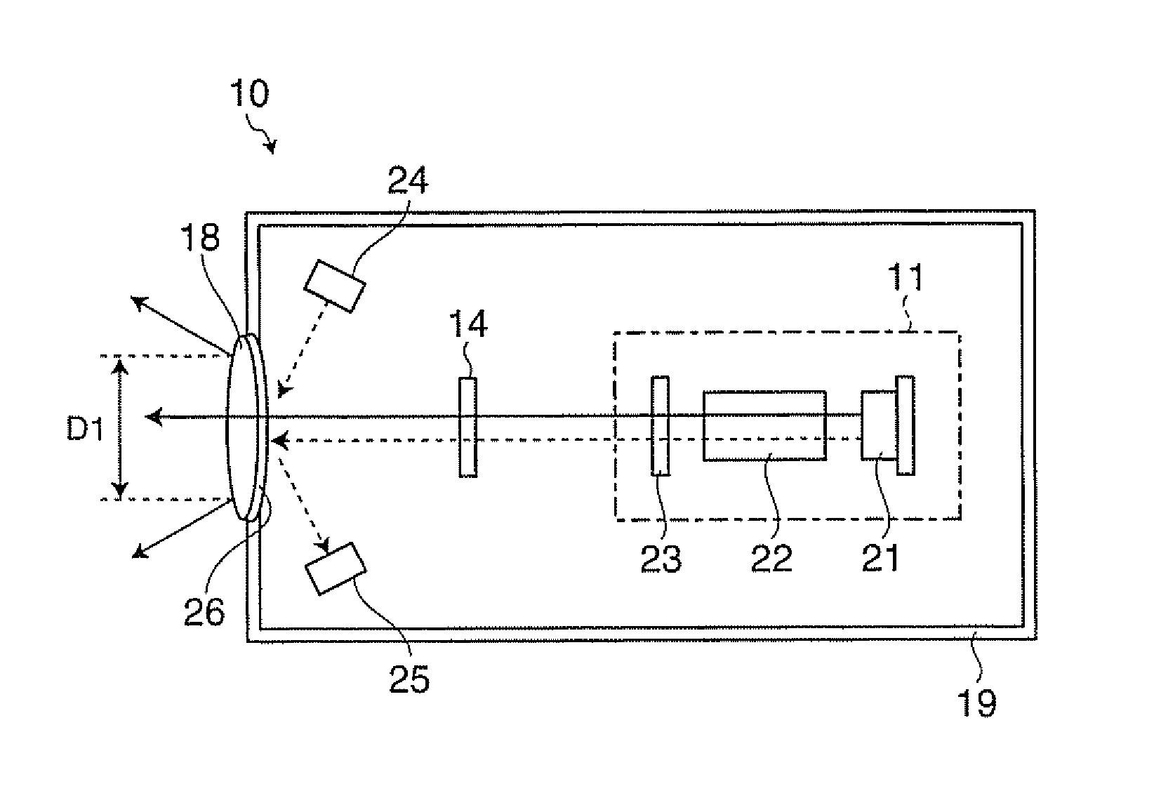
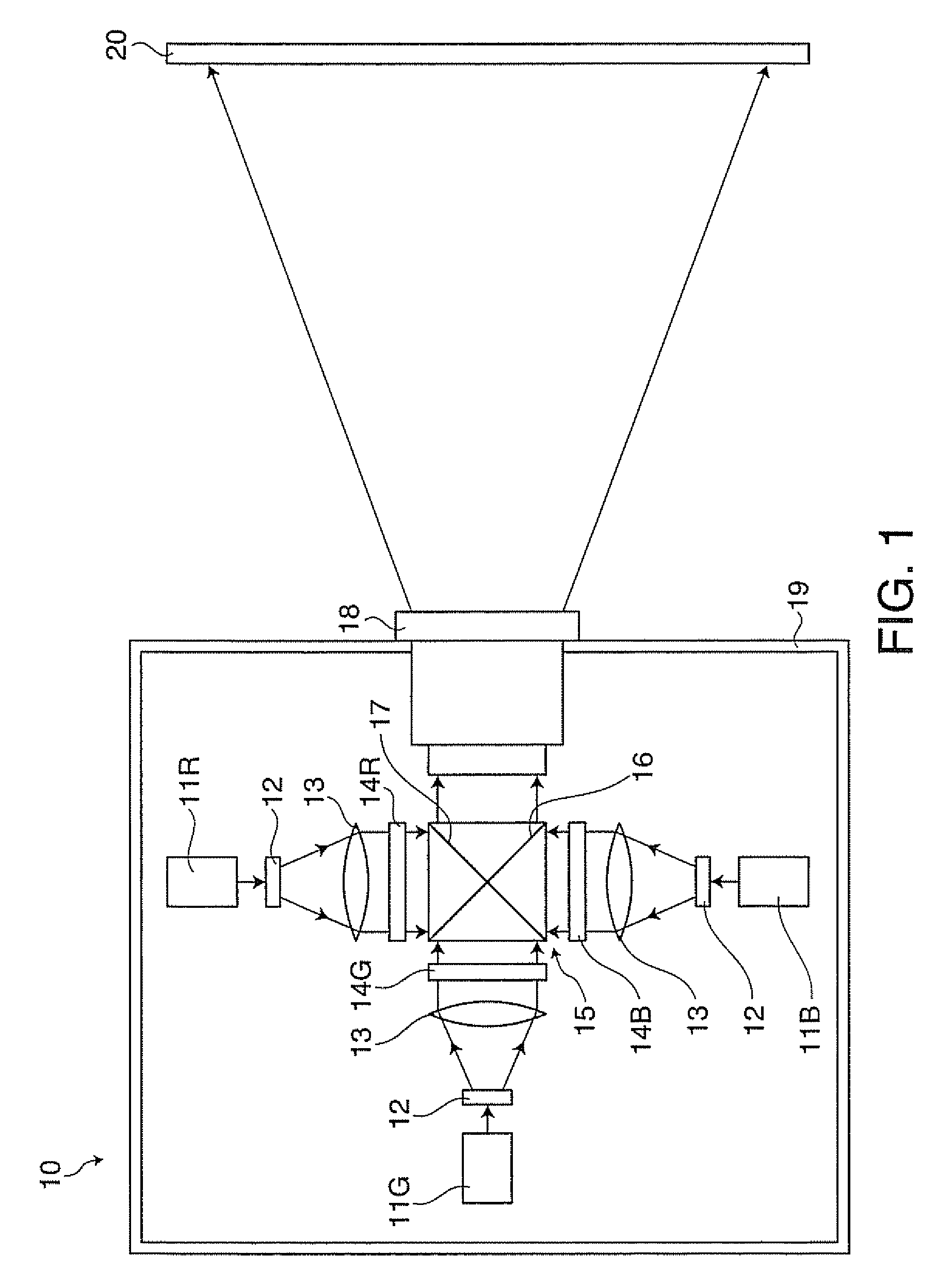
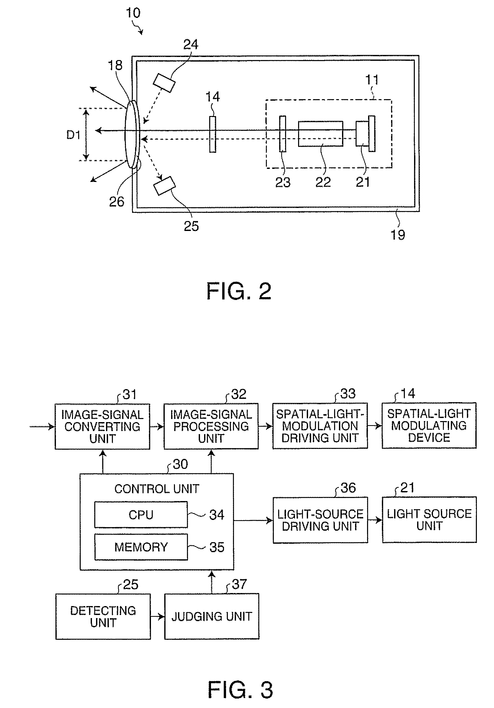
FIG. 1 is a diagram of a schematic configuration of a projector 10 according to a first embodiment of the invention. The projector 10 is a front projection projector that projects video light corresponding to an image signal onto a display surface of a screen 20. A user enjoys video by observing video light reflected on the screen 20. The projector 10 includes a light source device for red (R) light 11R, a light source device for green (G) light 11G, and a light source device for blue (B) light 11B. The light source device for R light 11R, the light source device for G light 11G, and the light source device for B light 11B are laser beam sources including semiconductor elements.

The light source device for R light 11R is a light source device that emits R light. A diffusing element 12 performs shaping and expansion of an illumination region and uniformalization of a light amount distribution in the illumination region. As the diffusing element 12, for example, a computer generated ho...

second embodiment

FIG. 5 is a diagram for explaining a projector 50 according to a second embodiment of the invention. Components same as those in the first embodiment are denoted by the same reference numerals and signs and redundant explanation of the components is omitted. The light source device 11, the spatial-light modulating device 14, the projection lens 51, the light source unit for detection 24, and the detecting unit 25 are stored in the inside of the housing 19. A transmitting unit 52 is provided to close the opening formed in the housing 19. The transmitting unit 52 is an optical element that transmits video light projected by the projection lens 51 and emits the video light toward the outside of the housing 19. The transmitting unit 52 is a transparent member formed in a plate shape. The transmitting and reflecting section 26 is formed on an incident surface on which the video light is made incident of the transmitting unit 52. The transmitting unit 52 is coated with not-shown AR coat f...

third embodiment

FIG. 8 is a diagram for explaining a projector 60 according to a third embodiment of the invention. Components same as those in the embodiments explained above are denoted by the same reference numerals and signs and redundant explanation of the components is omitted. Both of a first lens 61 and a second lens 62 are lenses configuring a projection optical system that projects video light. The light source device 11, the spatial- light modulating device 14, the first lens 61, the light source unit for detection 24, and the detecting unit 25 are stored in the housing 19. The second lens 62 is provided to close the opening formed in the housing 19. The second lens 62 is an optical element that transmits video light received from the first lens 61 and emits the video light toward the outside of the housing 19.

The transmitting and reflecting section 26 is formed on an incident surface of the second lens 62 on which video light is made incident. The second lens 62 is coated with not-shown...


PUM


Abstract

A projector that projects video light corresponding to an image signal onto a display surface includes: a light source device that emits light; a housing that houses at least the light source device; a projection lens, that is, an optical element that transmits the video light projected onto the display surface and emits the video light toward the outside of the housing; a detecting unit that detects detection light supplied to the optical element; and a control unit that adjusts a light amount of the video light on the basis of a result of the detection by the detecting unit. The projector is set such that, when the optical element is in a normal setting state, the light amount density of the video light is equal to or lower than a predetermined value on an emission surface for emitting the video light of the optical element.

Description

BACKGROUND1. Technical FieldThe present invention relates to a projector, and, more particularly to a technique for a projector that displays an image using a laser beam.2. Related ArtIn recent years, there is proposed a technique for using a laser beam source as a light source device for a projector. The laser beam source is developed as a light source for a projector according to an increase in power and an increase in colors. Compared with a UHP lamp used in the past as a light source for a projector, the laser beam source has advantages that, besides being small in size, for example, color reproducibility is high, instantaneous lighting is made possible, the durable life is long. It is possible to display a bright image by using the laser beam source with high power. On the other hand, it is necessary to take measures for preventing deficiencies that are likely to be caused by laser beams such as the influence of a laser beam affecting the eyes when the laser beam directly enter...

Claims


Application Information

Patent Timeline
Patent Type & Authority Patents(United States)
IPC IPC(8): G03B21/14
CPCH04N9/3129G03B21/2053G03B21/2033
Inventor KAMIJIMA, SHUNJI
Owner SEIKO EPSON CORP
Why Eureka
Try Eureka