

Joint for panels
a technology of joints and panels, applied in the field of joints, can solve the problems of radically reducing the useful life of the floor, affecting the assembly process, and affecting the use of the floor, so as to improve the assembly procedure and improve the locking between the panels
Inactive Publication Date: 2011-07-14
PERGO
View PDF7 Cites 149 Cited by
- Summary
- Abstract
- Description
- Claims
- Application Information
AI Technical Summary
Benefits of technology
"The present invention relates to a joint with improved assembly and locking between panels. The joint includes a first edge and a second edge with a moveable locking element. The locking element has a tongue and a cheek that press on the edges to create a snap-action cam lock effect. The joint can be used on floor panels or wall panels, and the upper surface can be a decorative paper or foil. The invention allows for easier assembly and better locking between panels."
Problems solved by technology
The most common types of tongue and groove are however burdened with the disadvantage to form gaps of varying width between the floor boards in cases where the installer hasn't been thorough enough.
The expansion will cause the surface layer to rise closest to the edges of the joint which radically reduces the useful life of the floor since the surface layer will be exposed to an exceptional wear.
This operation is however more or less awkward.
It is very common to use fibre board or particle board as core material and the resilient properties of these materials are somewhat limited.
Method used
View moreImage
Smart ImageViewing Examples

Examples
first embodiment
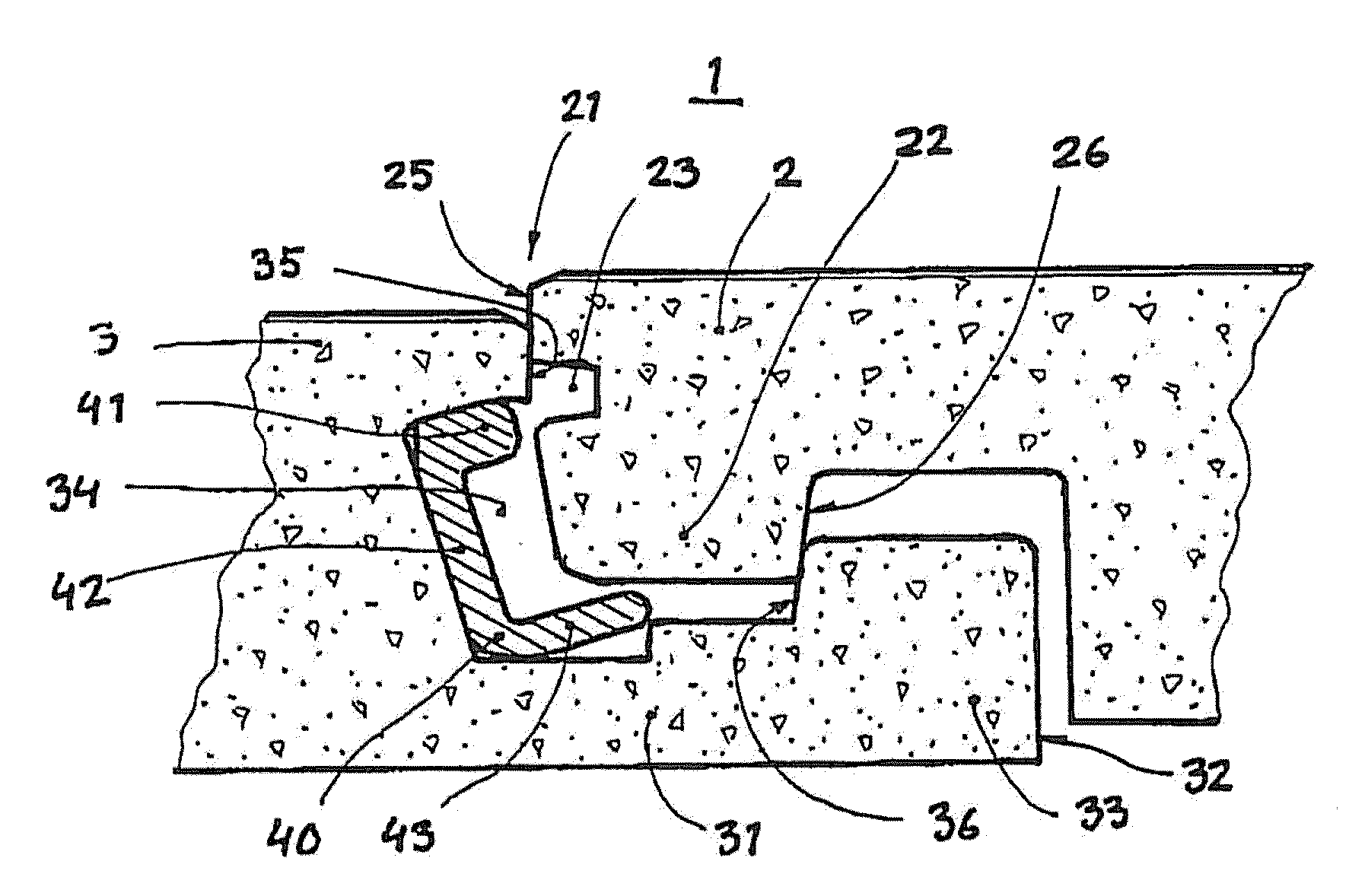
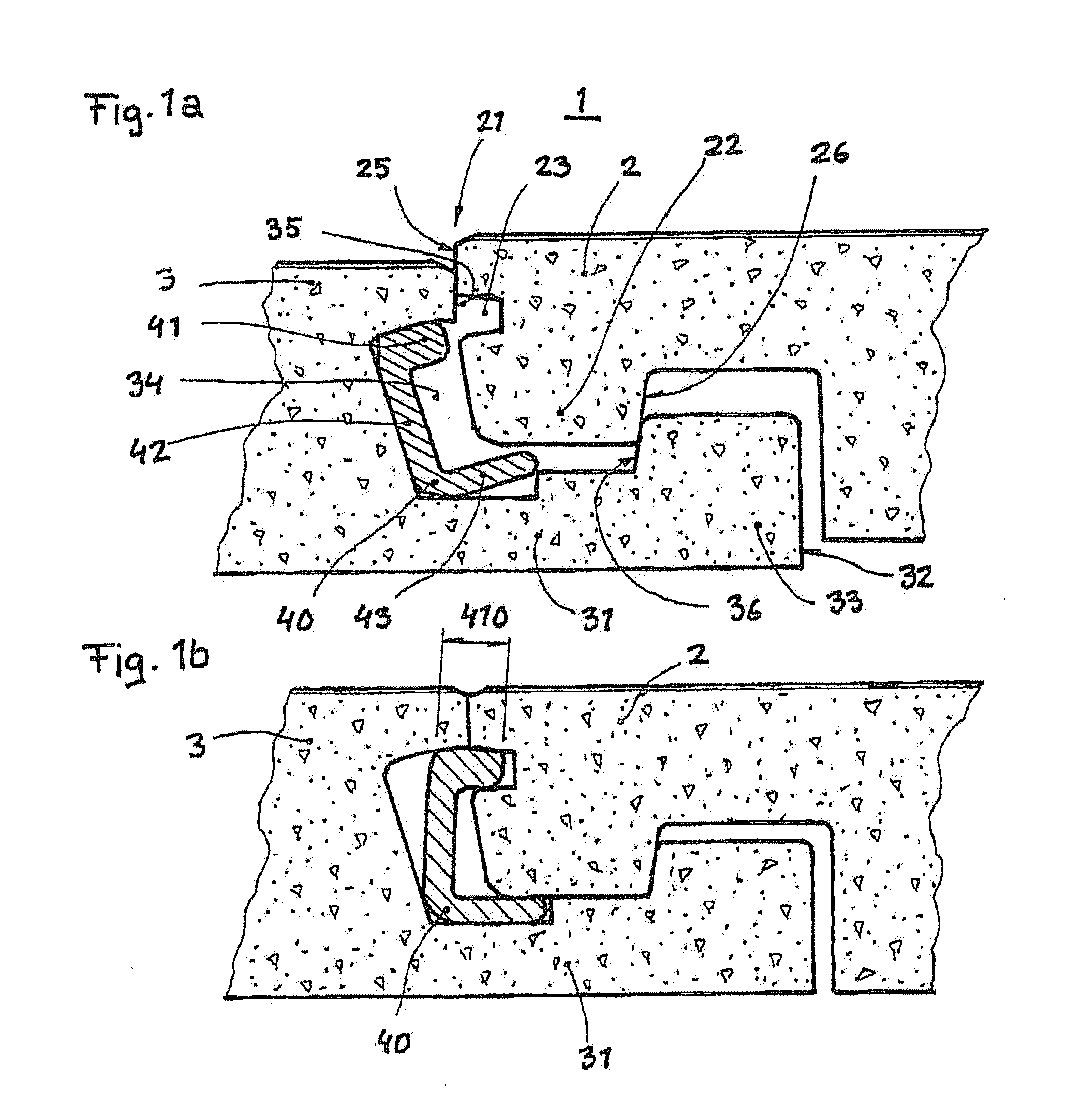
[0023]FIG. 1a-b shows a joint 1 according to the invention.
second embodiment
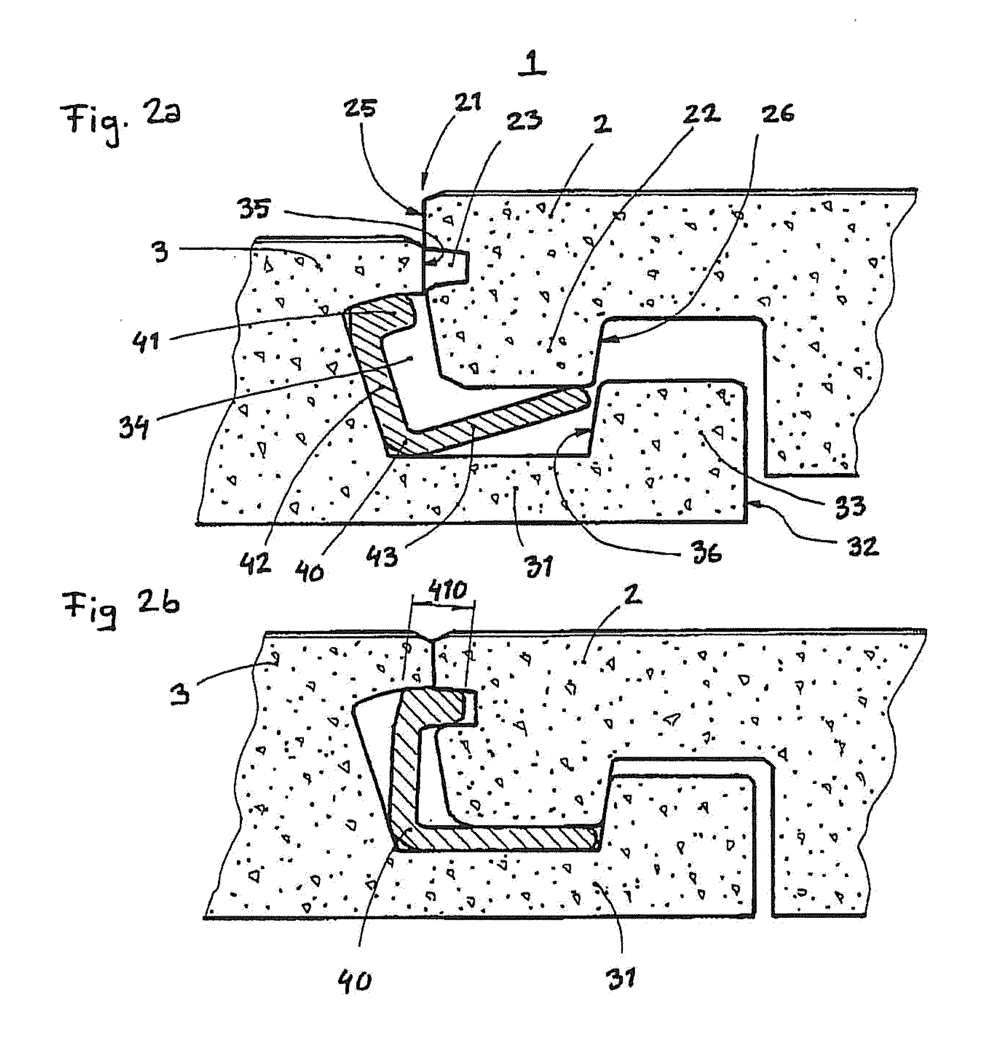
[0024]FIG. 2a-b shows a joint 1 according to the invention.
third embodiment
[0025]FIG. 3a-b shows a joint 1 according to the invention.
Login to View More PUM
| Property | Measurement | Unit |
|---|---|---|
| thermoplastic | aaaaa | aaaaa |
| density | aaaaa | aaaaa |
| width | aaaaa | aaaaa |
Abstract
A joint (1) having a first edge (2) and a second edge (3), the first edge (2) being provided with a distal edge (21) and a downwards protruding heel (22). The distal edge (21) is further provided with an upper joint edge (25) beneath which a groove (23) is arranged. The second edge (3) is provided with lower cheek (31) having a distal end (32) at which an upwards protruding lower cheek heel (33) is arranged. The second edge (3) is further provided with an upper joining edge (35) beneath which an undercut (34) is arranged. A moveable locking element (40) is arranged in the space created by the undercut (34). The moveable locking element (40) have a locking tongue (41), a locking tongue leg (42) and a maneuvering leg (43).
Description
CROSS-REFERENCE TO RELATED APPLICATIONS[0001]This application is a continuation of Ser. No. 11 / 242,127, filed Oct. 4, 2005; claiming the benefit of Swedish Application No. 0501639-9, filed Jul. 11, 2005, the entire disclosures of which are incorporated herein by reference.BACKGROUND OF THE INVENTION[0002]1. Field of the Invention[0003]The present invention relates to a joint used for connecting panels.[0004]2. Description of Related Prior Art[0005]Prefabricated floor boards provided with tongue and groove at the edges are quite common nowadays. These can be installed by the average handy man as they are very easy to install. Such floors can, for example, be constituted of solid wood, fibre board or particle board. These are most often provided with a surface layer such as lacquer, or some kind of laminate. The boards are most often installed by being glued via tongue and groove. The most common types of tongue and groove are however burdened with the disadvantage to form gaps of var...
Claims
Login to View More Application Information
Patent Timeline
 Patent Type & AuthorityApplications(United States)
IPC IPC(8): E04C2/38
CPCE04F15/02E04F2201/0115E04B5/00F16B5/0056E04F2201/0552E04F2201/0138E04F15/02005E04F2201/05E04C2/20E04C2/38E04F15/02038
InventorENGSTROM, NILS-ERIK
OwnerPERGO