Eureka AIR delivers breakthrough ideas for toughest innovation challenges, trusted by R&D personnel around the world.

Collapsible crate

Inactive Publication Date: 2011-07-14
THE NOT BOX
View PDF7 Cites 22 Cited by
  • Summary
  • Abstract
  • Description
  • Claims
  • Application Information

AI Technical Summary

Benefits of technology

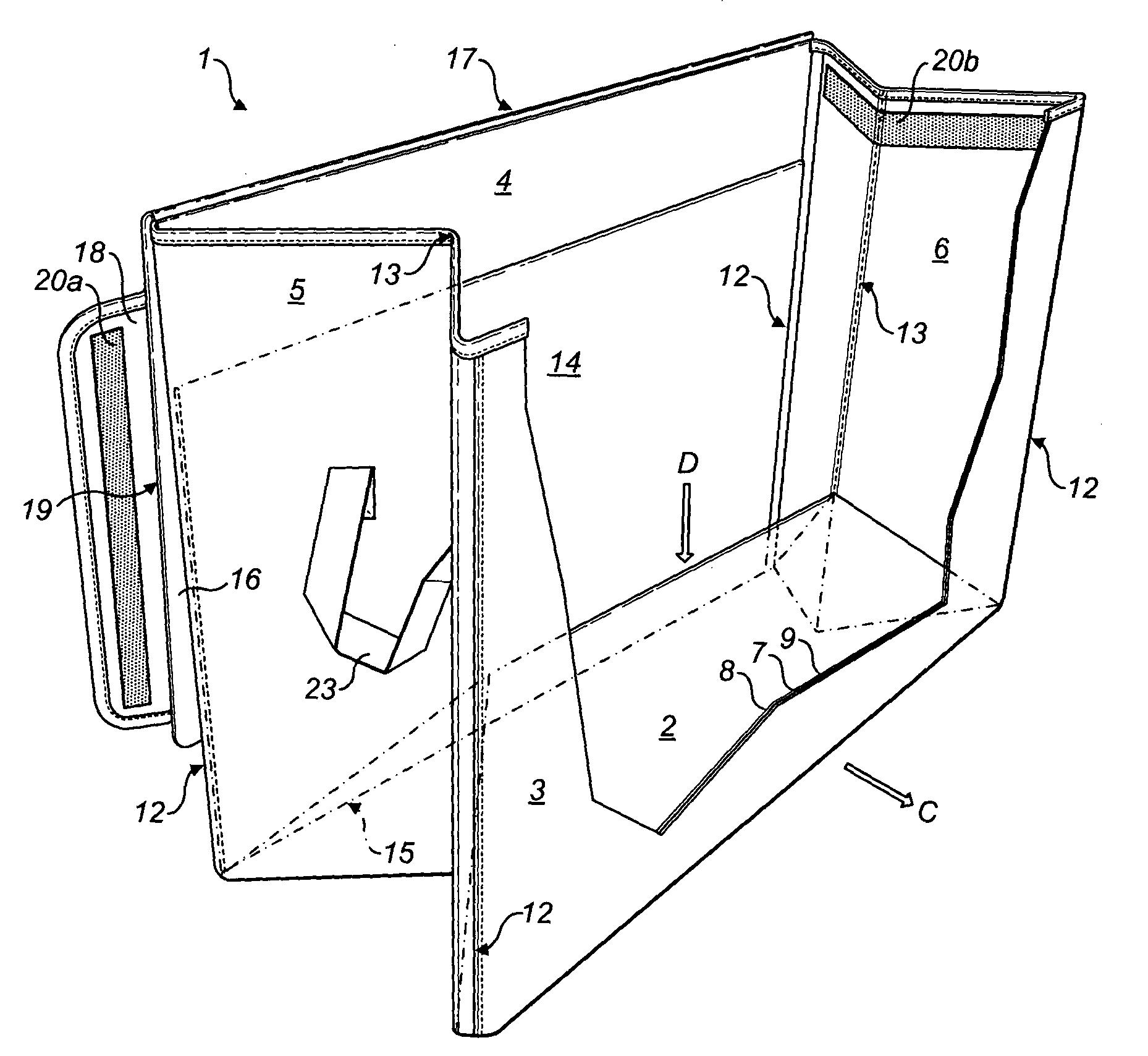
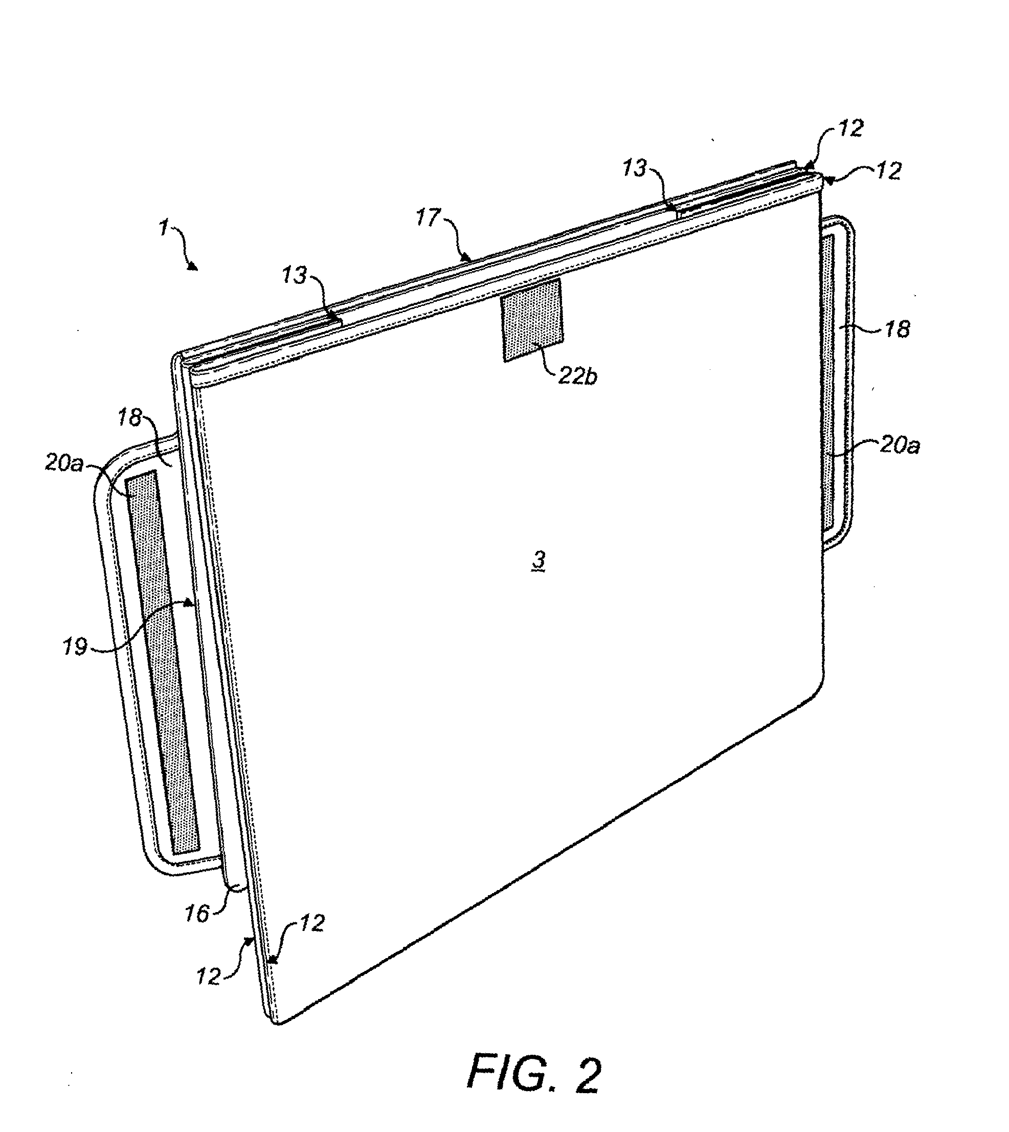
[0007]The present invention is advantageous in that the crate can be collapsed to a flat packed state and yet is easy to erect and has a sturdy construction suitable for stacking due to the integrity of the semi-rigid panel or panels of the sandwich construction. The hinges ensure that the collapsible crate maintains its integrity when collapsed from an erected state a plurality of times such that the collapsible crate in accordance with the present invention has a life cycle considerably greater than that of cardboard crates of typical construction that have been used to date. The flexible web of the base supports the semi-rigid flap of the crate when in an erected state as the flexible web is made taught between the at least two opposing walls to which the web is connected. However, the web is flexible and so can easily be gathered up within the crate when collapsed, ensuring that the crate is easier to erect from a flat packed state than prior art crates whilst at the same time providing at least the same, if not greater, stackability. The end walls fold inwardly about the upstanding hinges as the crate is collapsed.
[0008]Preferably, the base web is connected to the lower end of each of the side and end walls. This provides maximum support for the semi-rigid flap of the erected crate.
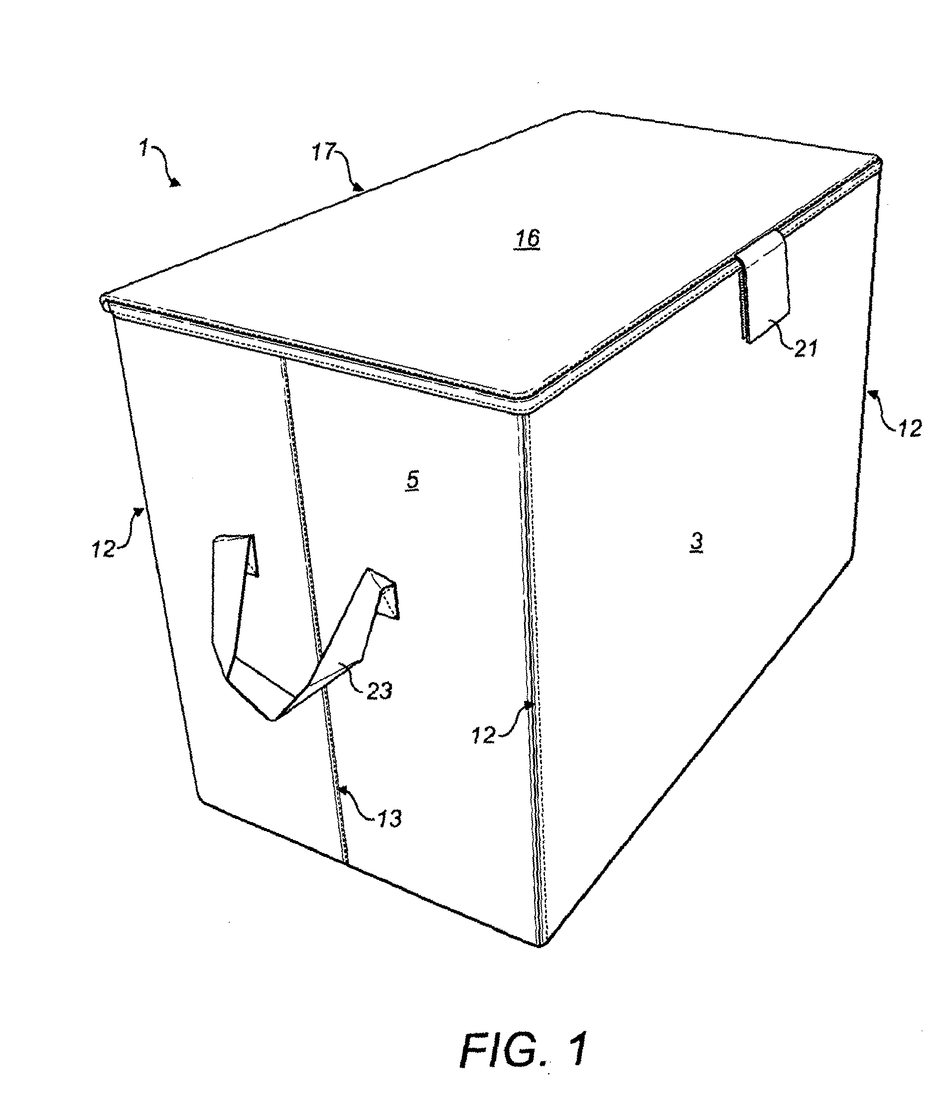
[0009]Preferably, the side and end walls are planar when the crate is in a constructed state. This allows the crate to be stacked easily and minimizes the storage space required when the crate is in a constructed state.
[0010]The base of the crate may be a rectangle. When the base of the crate is rectangular in shape it allows multiple crates to be easily stacked together reducing the requirements of the storage space and allows the crate to be collapsed to a flat packed state for ease of storing when the crate is collapsed.
[0013]Preferably, the semi-rigid flap further comprises a handle on the opposite side to the hinge for raising and lowering the flap when constructing and collapsing the crate. The addition of the handle to the flap allows the user to more easily raise and lower the flap when constructing and collapsing the crate. Typically, the handle will comprise a strip of fabric stitched to the side of the flap opposite to the hinge.
[0026]A second aspect of the present invention includes a stackable crate system comprising a first collapsible crate according to the first aspect of the present invention, a second collapsible crate according to the first aspect of the present invention wherein the second crate is adapted for insertion into and removal from the first crate. This allows separate compartments within the first crate to be created and allows smaller amounts of the contents to be removed from the first crate should the contents of the first or second crate be heavy.

Problems solved by technology

Cardboard crates are generally unsuitable for re-use due to the damage to the crate sustained during movements.
In recent years, retailers have taken their responsibilities with regard to the environment more seriously and it is no longer considered acceptable for millions of used cardboard crates to simply be thrown away in this manner.

Method used


Image

  • Collapsible crate
  • Collapsible crate
  • Collapsible crate

Examples


Embodiment Construction

[0043]With reference to FIGS. 1 to 6 and particularly FIG. 3, a stackable crate according to a first embodiment will now be described. Thereafter, a second embodiment constructed according to similar principles will be described. The crate 1 comprises a rectangular flexible web base 2, upstanding opposing semi-rigid side walls 3,4 and upstanding opposing semi-rigid end walls 5,6. The side walls 3,4 have a sandwich construction of a semi-rigid panel 7 between flexible webs 8, 9. The end walls have a sandwich construction of two semi-rigid panels 10 between flexible webs 11, 12. The construction of these walls will be further described with reference to FIG. 6.

[0044]The base flexible web 2 is stitched to the flexible webs of each of the side and end walls 3,4,5,6 so creating a seam at each juncture. The flexible webs of the side walls 3,4 are stitched to the flexible webs of the adjacent end walls 5,6, again forming a seam at each juncture. Upstanding hinges 12 are therefore formed at...


PUM


Abstract

A collapsible crate having a four sided base with at least one pair of parallel sides, upstanding opposing semi-rigid side walls and upstanding opposing semi-rigid end walls, the side walls being connected to the end walls via hinges, the base comprising a flexible web connected to the lower end of at least two of the opposing walls and a semi-rigid flap connected via a hinge to the lower end of one of the side walls such that the flap overlies and is supported by the flexible web when the crate is in a constructed state and is upstanding when the crate is in a collapsed state for flat packing, wherein the semi-rigid side and end walls and the flap each have a sandwich construction of a semi-rigid panel or panels between flexible webs, and wherein each end wall comprises at least two semi-rigid sections connected via a central upstanding hinge.

Description

CROSS REFERENCE TO RELATED APPLICATIONS[0001]This application is a continuation of U.S. application Ser. No. 12 / 738,605 filed Apr. 16, 2010, which application is incorporated herein by reference.FIELD OF THE INVENTION[0002]The present invention relates to a collapsible crate.BACKGROUND TO THE INVENTION[0003]At present, items, such as shoes, garments, underwear, toys etc, are transported from a factory in which they are manufactured to a retail outlet in crates made of corrugated cardboard. The flat packed cardboard crates are erected in the factory where they are filled with the items to be transported. The filled crates are typically stacked in a standard container for shipment by road, rail or air. Upon opening the container the filled crates are typically identified by electronic reading of a barcode of the like printed on the side of the crate whereupon the crate is automatically sensed by a magic eye, picked by grabbers and moved to a location for transport to its final destina...

Claims


Application Information

Patent Timeline
IPC IPC(8): B65D21/00B65D6/18
CPCB65D11/186
Inventor REES, GARYEMERSON, DAVID JOHNGLENN, KERRY ANN
Owner THE NOT BOX
Why Eureka
Eureka Blog
Learn More