Launch tube deployable surveillance and reconnaissance system

a launch tube and launch tube technology, applied in the direction of launching weapons, launching gear, transportation and packaging, etc., can solve the problems of exposing the operator to enemy fire, blast injury or other combat threats, toxic substances,

Inactive Publication Date: 2011-07-14
PFG IP +1
View PDF12 Cites 45 Cited by
  • Summary
  • Abstract
  • Description
  • Claims
  • Application Information

AI Technical Summary

Problems solved by technology

Current aerial vehicle launch systems typically require that the UAS operator physically enter the combat environment to launch the UAV thus exposing the operator to enemy fire, toxic substances, blast injury or other combat threats.

Method used


Image

  • Launch tube deployable surveillance and reconnaissance system
  • Launch tube deployable surveillance and reconnaissance system
  • Launch tube deployable surveillance and reconnaissance system

Examples


Embodiment Construction

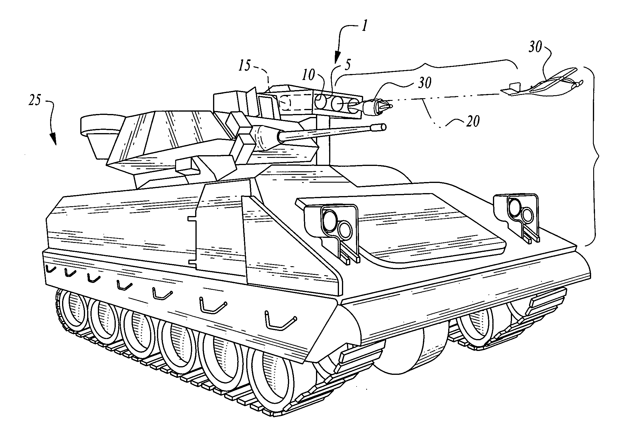
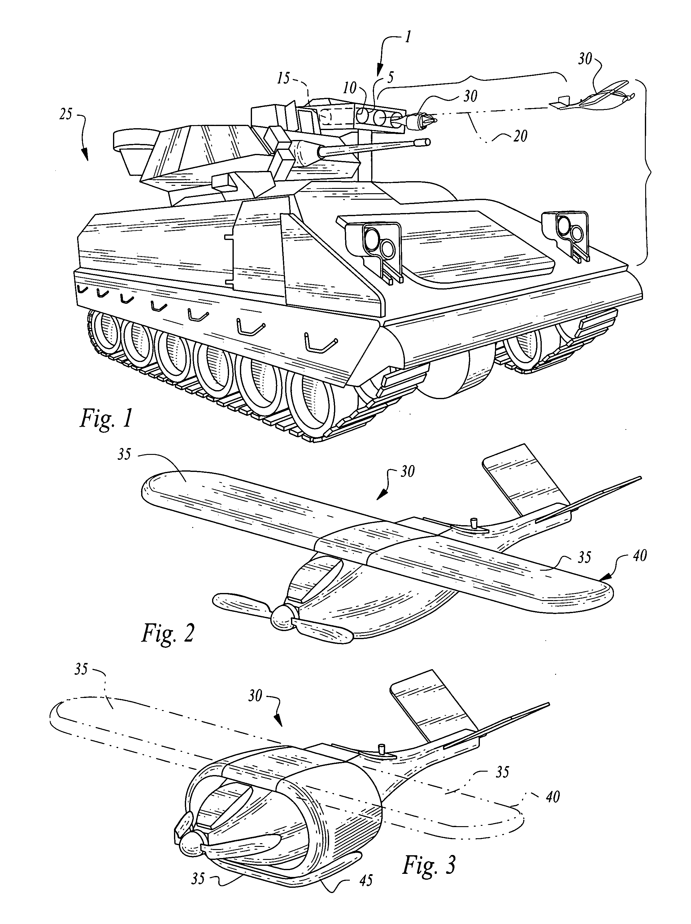
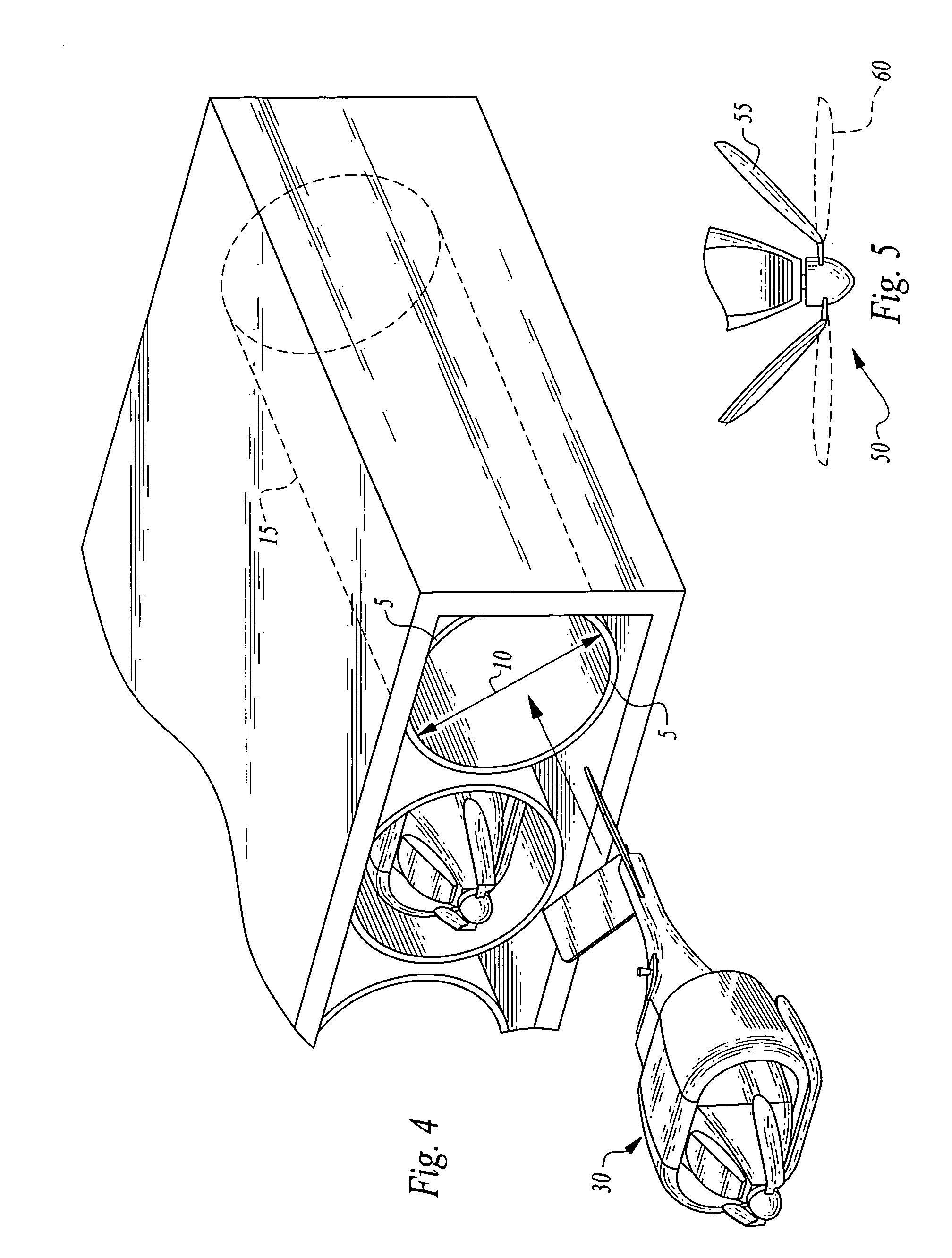
[0019]Turning now to the figures wherein like numerals define like elements among the several views, FIG. 1 depicts a preferred embodiment of the invention comprising a launch tube system 1 comprising a barrel 5 having a bore aperture 10 and a bore 15 having a longitudinal axis 20.

[0020]Launch tube system 1 is mounted on a mobile vehicle 25, in this embodiment, an armored combat vehicle such as a Stryker vehicle, Bradley fighting vehicle, tank or the like. In the depicted embodiment, the launch tube system is a TOW missile system (i.e., tube-launched, optically-tracked, wire data link, guided missile). By way of example and not by limitation, mobile vehicle 25 may be any mobile vehicle system such as a jeep, Humvee, armored personnel carrier, watercraft, amphibious craft or airborne vehicle such as a helicopter.

[0021]The invention further comprises an unmanned aerial vehicle (“UAV” herein) such as a remotely-operated, self-propelled aerial vehicle having suitable electronics for a u...


PUM


Abstract

An unmanned aerial surveillance and reconnaissance system are disclosed wherein an unmanned aerial vehicle is launchable from a launch tube, for instance, the bore of an existing weapons system mounted on a mobile vehicle, such as a weapon barrel of a tank or armored combat vehicle and which the launch may be remotely initiated from the protected armored compartment of the mobile vehicle.

Description

CROSS-REFERENCE TO RELATED APPLICATIONS[0001]This application claims the benefit of U.S. Provisional Patent Application No. 61 / 214,812, filed on Apr. 27, 2009 entitled “Weapon-Bore Launched Unmanned Aerial System and Device for Launching Same” pursuant to 35 USC 119, which application is incorporated fully herein by reference.STATEMENT REGARDING FEDERALLY SPONSORED RESEARCH AND DEVELOPMENT[0002]N / ADESCRIPTION[0003]1. Field of the Invention[0004]The invention relates generally to the field of unmanned aerial systems. More specifically, the invention relates to an unmanned aerial surveillance and reconnaissance system and vehicle that is launchable from, for instance, the bore of a separately provided existing weapons system mounted on a mobile vehicle and which launch may be remotely initiated from an armored compartment of the mobile vehicle.[0005]2. Background of the Invention[0006]Current military surveillance and reconnaissance efforts rely heavily on unmanned aerial vehicles and...

Claims


Application Information

Patent Timeline
Patent Type & Authority Applications(United States)
IPC IPC(8): B64F1/04
CPCB64C39/028B64C2201/203B64C2201/042B64C2201/084B64C2201/102B64C2201/127B64C2201/165F41A23/42F41B7/00F41B11/62F41F3/042F41F3/052F41F7/00F42B10/16F42B15/08B64C2201/201B64C2201/021B64U70/70B64U30/12B64U10/25B64U50/19B64U50/13B64U80/60B64U80/70B64U2101/30
Inventor HORNBACK, WILLIAMHOLLY, MICHAEL
Owner PFG IP
Why Eureka
Try Eureka