Testing system for power supply unit

a power supply unit and testing system technology, applied in power supply testing, instruments, measurement devices, etc., can solve the problems of cumbersome and power-consuming typical testing systems

Inactive Publication Date: 2011-07-14
HONG FU JIN PRECISION IND (SHENZHEN) CO LTD +1
View PDF4 Cites 19 Cited by
  • Summary
  • Abstract
  • Description
  • Claims
  • Application Information

AI Technical Summary

Problems solved by technology

However, the typical testing system is cumbersome and power-consuming.

Method used


Image

  • Testing system for power supply unit
  • Testing system for power supply unit
  • Testing system for power supply unit

Examples


Embodiment Construction

The disclosure is illustrated by way of example and not by way of limitation. In the figures of the accompanying drawings in which like references indicate similar elements. It should be noted that references to “an” or “one” embodiment in this disclosure are not necessarily to the same embodiment, and such references mean at least one.

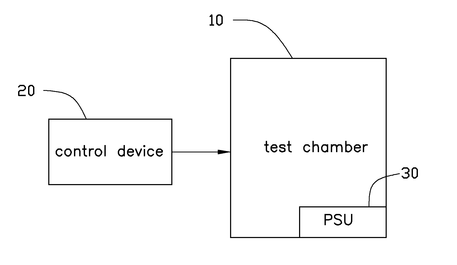
Referring to FIG. 1, an embodiment of a testing system includes a test chamber 10 and a control device 20 connected to the test chamber 10. The test chamber 10 and the control device 20 can perform a burn-in test and a power cycling test to a PSU 30 accommodated in the test chamber 10.

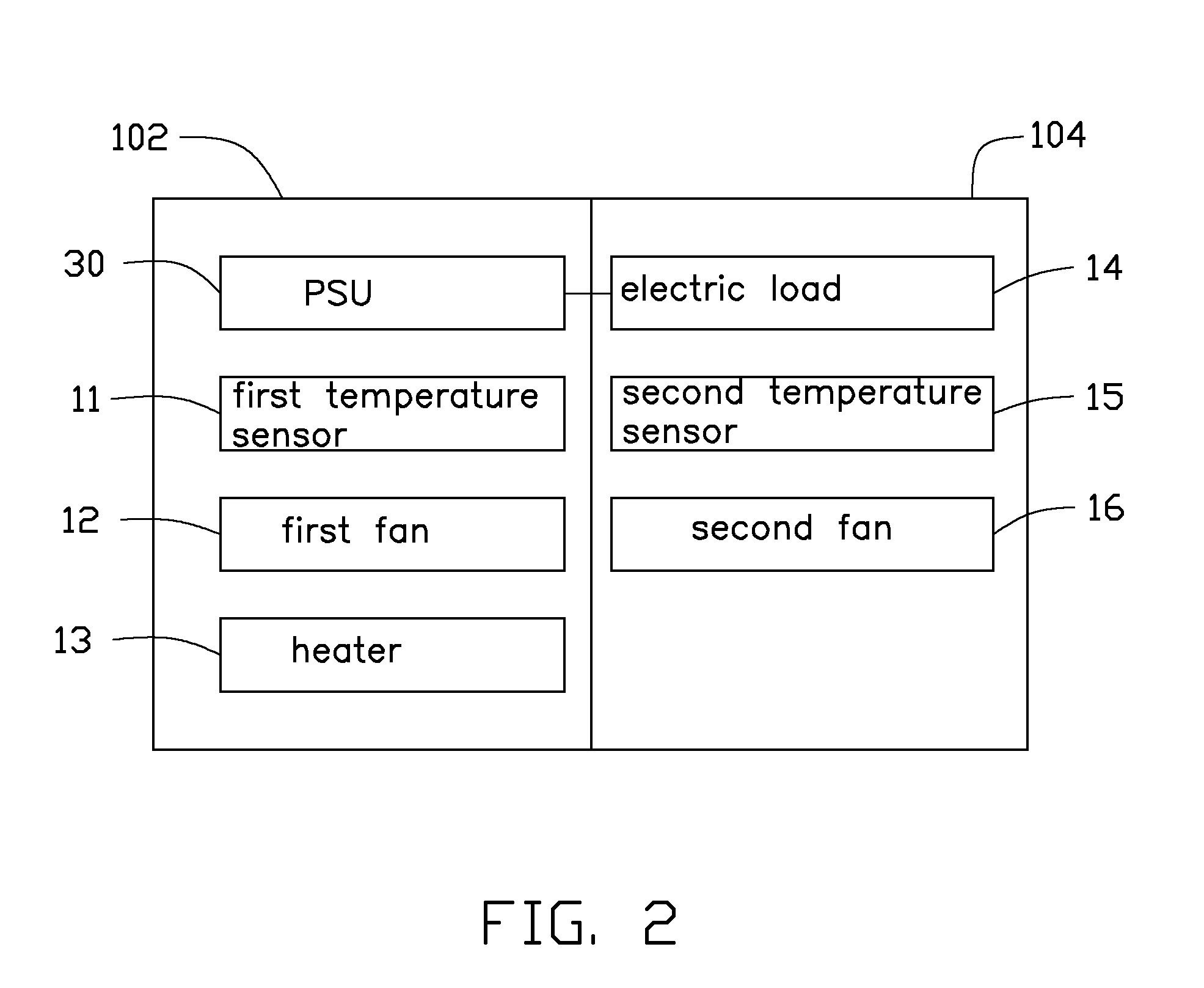
Referring to FIG. 2, the test chamber 10 includes a first partition 102 and a second partition 104. The PSU 30 is placed in the first partition 102. A first temperature sensor 11, a first fan 12, and a heater 13 are installed in the first partition 102. The first temperature sensor 11 is configured to sense a temperature in the first partition 102. The control device 20 ...


PUM


Abstract

A testing system for a PSU includes a test chamber and a control device. The test chamber includes a first partition with the PSU accommodated therein and a second partition with an electric load accommodated therein. The PSU is electrically connected to the electric load. The control device includes a microcontroller unit (MCU). The MCU is connected to a setting circuit and a temperature sensing circuit. The setting circuit is configured to set one of predetermined parameters. The temperature sensing circuit is capable of sensing temperature in the test chamber. The MCU is capable of automatically controlling a predetermined temperature in the test chamber and presetting a test time for testing the PSU.

Description

BACKGROUND1. Technical FieldThe present disclosure relates to a testing system for testing a power supply unit (PSU).2. Description of Related ArtA PSU is an electric device capable of converting an alternating current (AC) source to a plurality of direct current (DC) output voltages to a load (e.g., personal computer). Before the PSU is used in the personal computer, the PSU should pass several tests (e.g., burn-in test, power cycling test, etc). A typical testing system includes a test chamber and a control device connected to the test chamber. A plurality of PSUs can be placed in the test chamber. An operator can operate buttons of the control device to preset a test time and a temperature in the test chamber. Then the testing system can performs the burn-in test and the power cycling test to the plurality of PSUs. However, the typical testing system is cumbersome and power-consuming.BRIEF DESCRIPTION OF THE DRAWINGSFIG. 1 is a block diagram of a testing system for testing a PSU ...

Claims


Application Information

Patent Timeline
Patent Type & Authority Applications(United States)
IPC IPC(8): G01R31/40
CPCG01R31/40G01R31/2849
Inventor XIE, LING-YU
Owner HONG FU JIN PRECISION IND (SHENZHEN) CO LTD
Why Eureka
Try Eureka