Automated Medical Imaging System Fault Detection

a medical imaging and automatic technology, applied in the field of automatic medical imaging system fault detection, can solve the problems of limiting the effectiveness and timeliness of field repairs, lack of capability to store status and error data, etc., and achieve the effect of accelerating diagnosis and correction of faults and facilitating diagnosis and correction

Inactive Publication Date: 2011-07-14
SIEMENS HEALTHCARE GMBH
View PDF10 Cites 22 Cited by
  • Summary
  • Abstract
  • Description
  • Claims
  • Application Information

AI Technical Summary

Benefits of technology

[0004]A system automatically detects and reports a hardware and / or software error in an X-ray imaging system and graphically indicates on a display a particular component that has experienced the failure to facilitate and accelerate diagnosis and correction of the fault. A system automatically detects and identifies failed components of a distributed X-ray imaging system. Multiple different subsystems of an X-ray imaging system individually include, an executable procedure for detecting a failed component in a respective subsystem and a communication interface for initiating generation and communication of a message identifying the failed component and identifying the respective subsystem including the failed component. A repository stores data identifying failed components within the multiple different subsystems in response to the communicated message. An error processor accesses the repository of data and provides composite information enabling a user to identify failed components within an X-ray imaging system.

Problems solved by technology

Many of these subsystems are embedded systems that have little or no storage capability and limited error reporting capability.
This often involves an engineer thus limiting the effectiveness and timeliness of repairs in the field and resulting in engineering personnel working with field service to recreate different scenarios to determine what might have happened to cause an error.
X-Ray imaging system components comprise multiple sub-components which are employed by X-ray system operational processes and typically lack a capability to store status and error data.

Method used


Image

  • Automated Medical Imaging System Fault Detection
  • Automated Medical Imaging System Fault Detection
  • Automated Medical Imaging System Fault Detection

Examples


Embodiment Construction

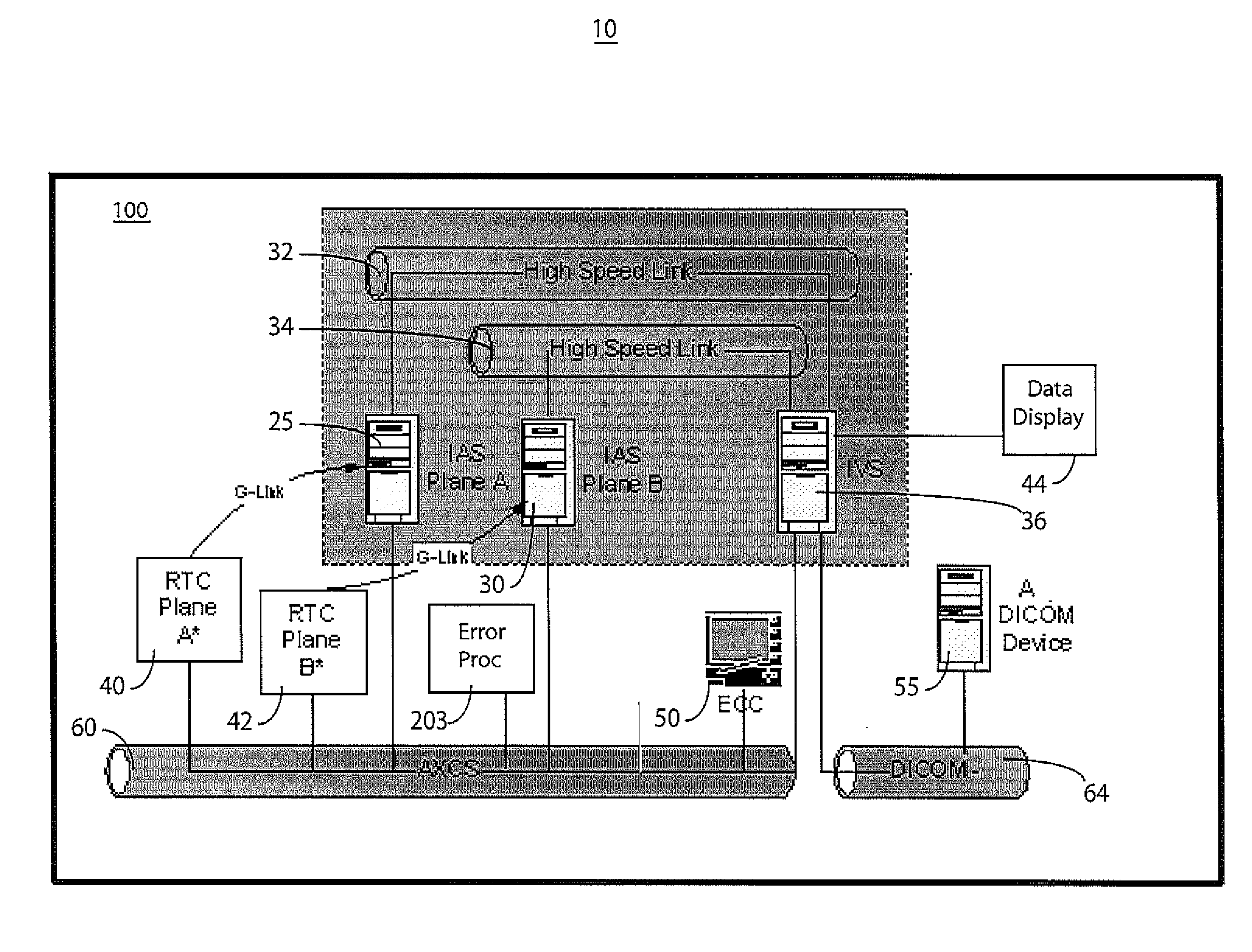
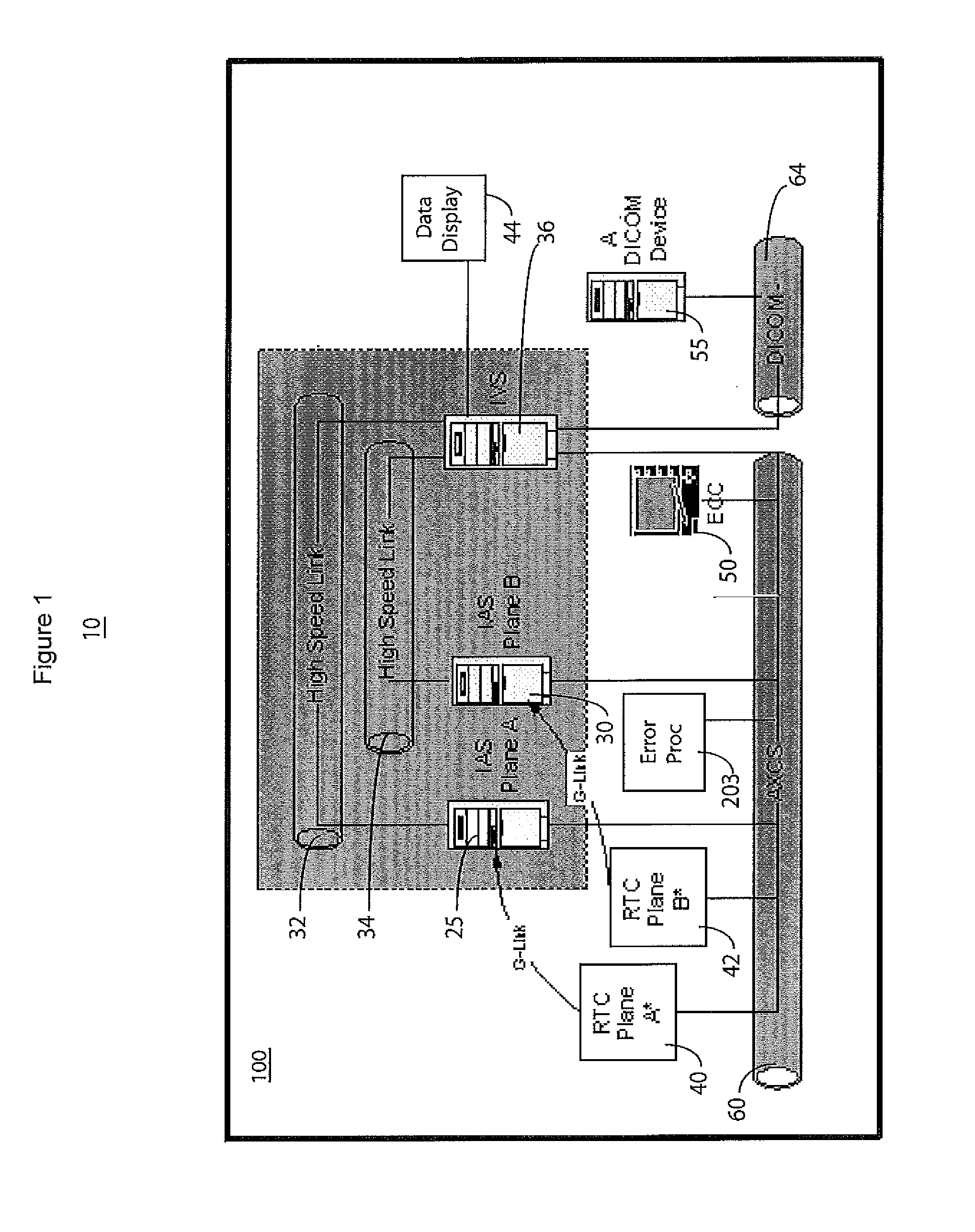
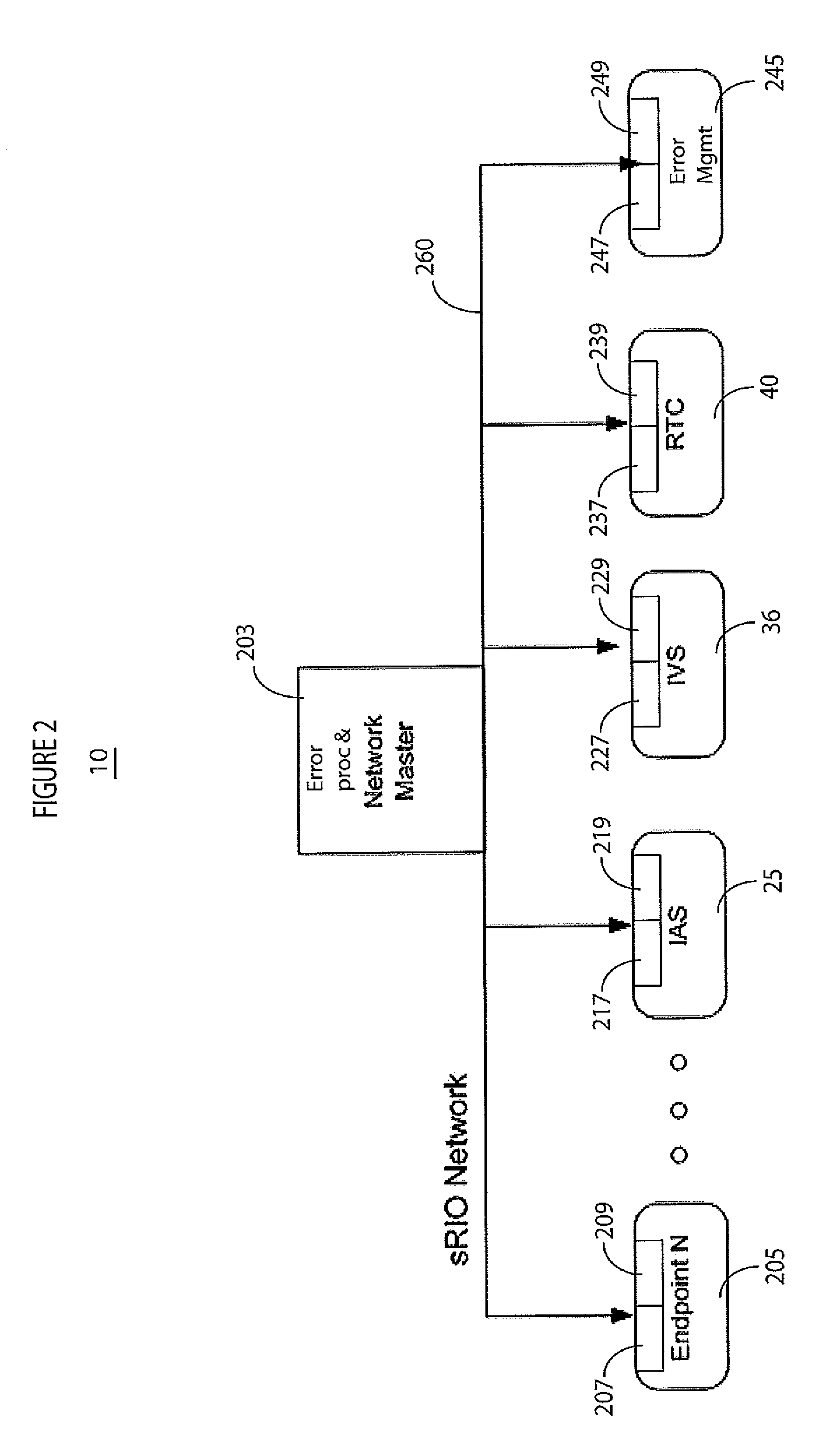
[0010]The inventor has advantageously recognized the need for a system to automatically detect and report a failure in a medical imaging system and that this may be facilitated by use of particular communication protocols such as an sRIO protocol. The Serial RapidIO (SRIO) protocol standard and associated RapidIO specification is a packet-based protocol that is employed by endpoints, which originate and process digital data packets and is employed by switches, which are used to connect endpoints. RapidIO is a layered specification, divided into a physical layer protocol, packet transport (routing) protocol and multiple protocols in a logical layer. An sRIO message is employed as part of this protocol. Subsystems are connected to an sRIO network as endpoints. A system according to invention principles in one embodiment advantageously employs the sRIO protocol and sRIO message capability, for example, to automatically detect and report a failure.

[0011]FIG. 1 shows a biplane X-ray syst...


PUM


Abstract

A system automatically detects and reports a hardware and / or software error in an X-ray system. A system automatically detects and identifies failed components of a distributed X-ray imaging system. Multiple different subsystems of an X-ray imaging system individually include, an executable procedure for detecting a failed component in a respective subsystem and a communication interface for initiating generation and communication of a message identifying the failed component and identifying the respective subsystem including the failed component. A repository stores data identifying failed components within the multiple different subsystems in response to the communicated message. An error processor accesses the repository of data and provides composite information enabling a user to identify failed components within an X-ray imaging system.

Description

[0001]This is a non-provisional application of provisional application Ser. No. 61 / 294,968 filed 14 Jan. 2010, by D. St. John et al.FIELD OF THE INVENTION[0002]This invention concerns a system for automatic detection and identification of failed components of a distributed X-ray imaging system, for example.BACKGROUND OF THE INVENTION[0003]An X-ray imaging system includes multiple hardware and software subsystems. Each of these subsystems is typically divided into components. Many of these subsystems are embedded systems that have little or no storage capability and limited error reporting capability. When there is a problem in the field, multiple people associated with different subsystems are needed to investigate an issue, (e.g. an error or failure) involving review of scattered, distributed and disjointed log information to ascertain where an error occurred and why. This often involves an engineer thus limiting the effectiveness and timeliness of repairs in the field and resultin...

Claims


Application Information

Patent Timeline
Patent Type & Authority Applications(United States)
IPC IPC(8): H05G1/64
CPCA61B6/586A61B6/461
Inventor RUGGIERO, THOMASST. JOHN, DANIEL
Owner SIEMENS HEALTHCARE GMBH
Why Eureka
Try Eureka