
Golf club shaft and golf club

a golf club and shaft technology, applied in the field of golf club shafts, can solve the problems of not allowing one of the shafts to primarily operate, low stiffness at this non-overlapping part, and high friction, so as to increase the initial speed of the ball, increase the launch angle of the ball, and increase the driving distance

Inactive Publication Date: 2011-07-14
BRIDGESTONE SPORTS
View PDF26 Cites 2 Cited by
  • Summary
  • Abstract
  • Description
  • Claims
  • Application Information

AI Technical Summary

Benefits of technology

[0007]The present invention has been made under the above circumstances. The present invention is a golf club shaft which has a double structure including an outer shaft and an inner shaft, and which allows both of the shafts to integrally operate and also allows one of the shafts to primarily operate. An object of the present invention is to provide a golf club shaft that exhibits excellent performance by these operations of such shafts and to provide a golf club using the golf club shaft.
[0009]In the golf club shaft of the present invention, the outer shaft and the inner shaft are separate bodies from each other. In addition, the outer shaft and the inner shaft are apart from each other. Thereby, the outer shaft and the inner shaft can operate independently. Thus, when a golfer slow in head speed swings the golf club of the present invention, the outer shaft flexes, but the inner shaft does not flex at all or flexes little depending on the head speed. Accordingly, the shaft as a whole is flexible and suitable for a golfer slow in head speed. The flexibility of the shaft is utilized to increase the head speed or to increase the launch angle of a ball; thereby, the driving distance can be increased. In contrast, when a golfer fast in head speed swings the golf club of the present invention, both of the shafts flex together greatly. Accordingly, the shaft as a whole is stiff and suitable for a golfer fast in head speed. The stiffness of the shaft is utilized to increase the initial speed of a ball; thereby, the driving distance can be increased.
[0011]When a golfer slow in head speed swings the golf club with the golf club shaft of the present invention, the shaft is flexible while primarily the outer shaft flexes. This allows increase in a launch angle of a ball and thus allows increase in the driving distance. Meanwhile, when a golfer fast in head speed swings the golf club with the golf club shaft of the present invention, the shaft is stiff while the outer shaft and the inner shaft flex together. This allows increase in the initial speed of a ball and thus allows increase in the driving distance.

Problems solved by technology

The stiffness at this non-overlapping part is low, and there is likely to be flexing.
This allows both of the shafts to integrally operate but does not allow one of the shafts to primarily operate.

Method used


Image

  • Golf club shaft and golf club
  • Golf club shaft and golf club
  • Golf club shaft and golf club

Examples


first embodiment

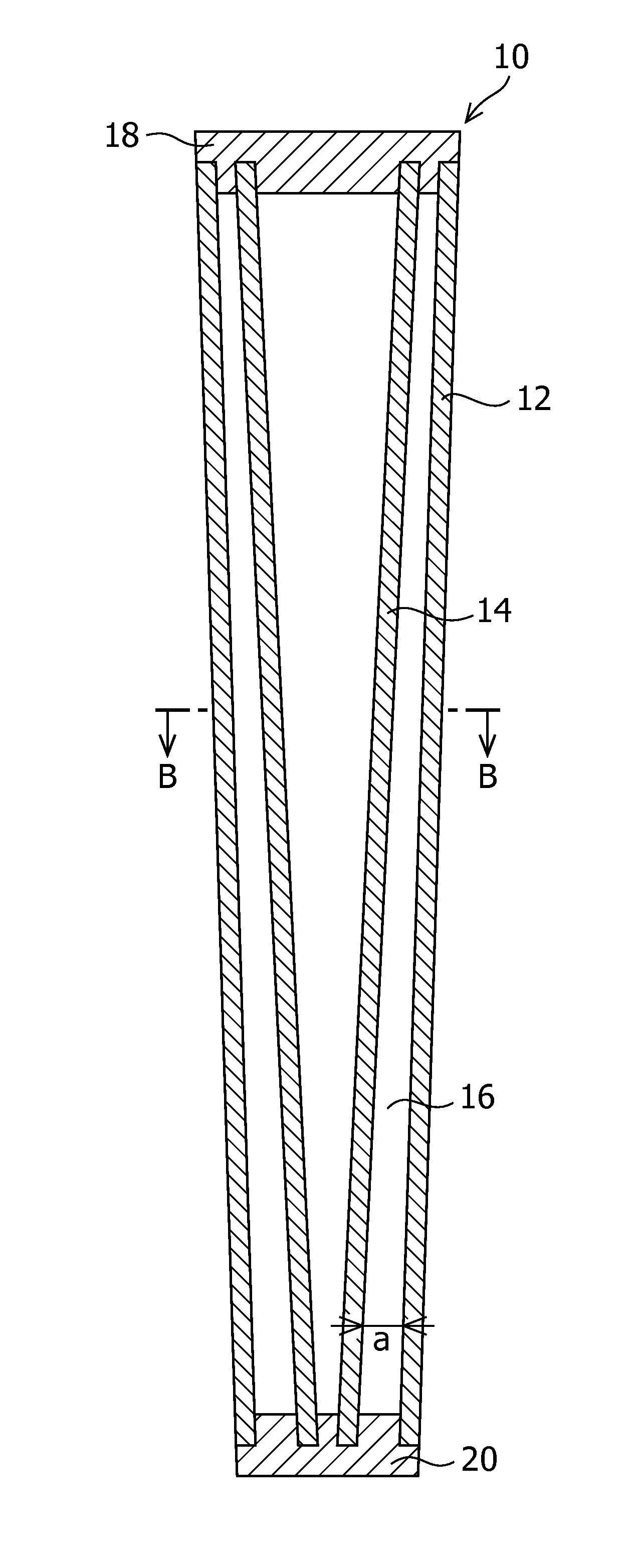
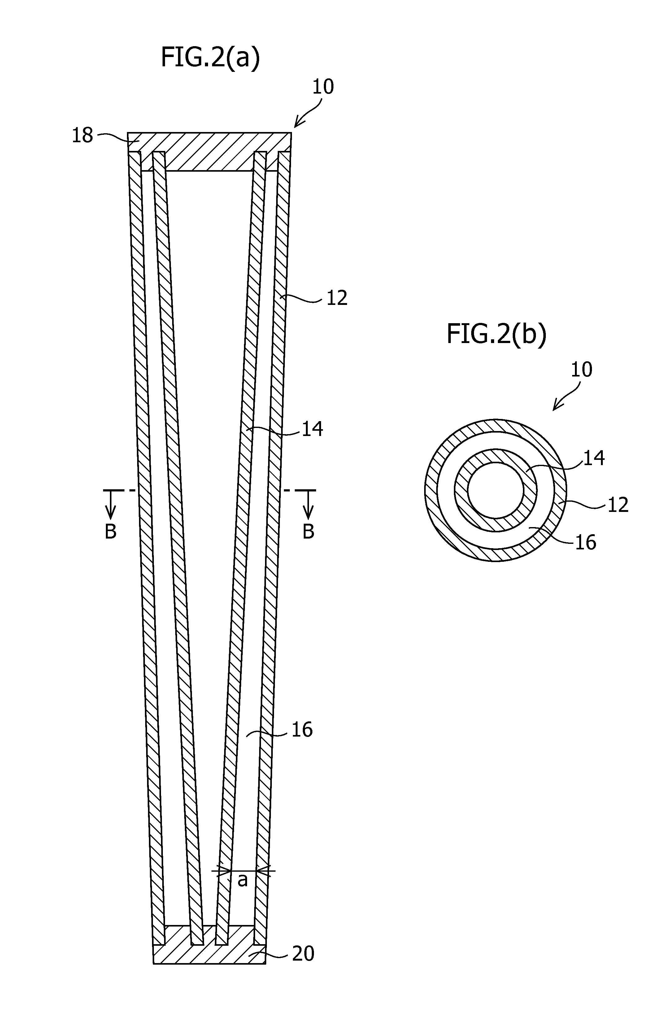
[0025]FIGS. 1, 2A and 2B illustrate a first embodiment of a golf club shaft according to the present invention. In FIGS. 2A and 2B, a grip 11 is not illustrated. A shaft 10 of the first embodiment includes an outer shaft 12 and an inner shaft 14 disposed in a hollow portion of the outer shaft 12. A void portion 16 is formed between the outer shaft 12 and the inner shaft 14. In the first embodiment, each of the outer shaft 12 and the inner shaft 14 has a hollow tapered conical shape such that the diameter is gradually reduced toward the tip end. The outer shaft 12 and the inner shaft 14 have almost equal lengths. The outer shaft 12 preferably has a length with a lower limit of approximately 787 mm and an upper limit of approximately 1219 mm. The outer shaft 12 preferably includes a distal end having an outer diameter with a lower limit of approximately 8.4 mm and an upper limit of approximately 10 mm; a proximal end having an outer diameter with a lower limit of approximately 14 mm a...

second embodiment

[0032]FIGS. 3A and 3B illustrate a second embodiment of a golf club shaft according to the present invention. In FIGS. 3A and 3B, a grip 11 is not illustrated. A shaft 30 of the second embodiment includes an outer shaft 12 and an inner shaft 14 disposed in a hollow portion of the outer shaft 12. A void portion 16 is formed between the outer shaft 12 and the inner shaft 14. In the second embodiment, the outer shaft 12 has such a hollow tapered conical shape that the diameter is gradually reduced toward the tip end. The inner shaft 14 has such a hollow cylindrical shape that the diameter at the proximal end is the same as the diameter at the distal end. The outer shaft 12 and the inner shaft 14 have almost equal lengths. The outer shaft 12 and the inner shaft 14 may each have a length, outer diameter, and thickness of the wall portions which are the same as those in the first embodiment.

[0033]The void portion 16 has a width a, at the distal end, with a lower limit of preferably approx...

third embodiment

[0035]FIGS. 4A and 4B illustrate a third embodiment of a golf club shaft according to the present invention. In FIGS. 4A and 4B, a grip 11 is not illustrated. A shaft 40 of the third embodiment includes an outer shaft 12 and an inner shaft 14 disposed in a hollow portion of the outer shaft 12. A void portion 16 is formed between the outer shaft 12 and the inner shaft 14. In the third embodiment, the outer shaft 12 has such a hollow tapered conical shape that the diameter is gradually reduced toward the tip end. The inner shaft 14 has such a solid cylindrical shape that the diameter at the proximal end is the same as the diameter at the distal end. The outer shaft 12 and the inner shaft 14 have almost equal lengths. The outer shaft 12 may have the same length, outer diameter, and thickness of the wall portions as that in the first embodiment. The inner shaft 14 may have the same length and outer diameter as that in the first embodiment.

[0036]The void portion 16 has a width a, at the ...


PUM


Abstract

A golf club shaft includes an outer shaft and an inner shaft disposed in a hollow portion of the outer shaft. A void portion is formed between the outer shaft and the inner shaft. The golf club shaft has a double structure including the outer shaft and the inner shaft. This allows both of the shafts to integrally operate and also allows one of the shafts to primarily operate.

Description

CROSS-REFERENCE TO RELATED APPLICATION[0001]This application claims priority on Japanese Patent Application No. 2010-004567 filed Jan. 13, 2010, which is incorporated herein by reference in its entirety.BACKGROUND OF THE INVENTION[0002]The present invention relates to a golf club shaft having a double structure including an outer shaft and an inner shaft, and to a golf club using the golf club shaft.[0003]Japanese Patent No. 3647034 has previously proposed a golf club shaft having a double structure including an outer shaft and an inner shaft. A golf club shaft according to claim 1 in the publication includes an outer shaft and an inner shaft inserted in the outer shaft. The outer shaft and the inner shaft each have such a tapered shape that the diameter is smaller at the distal end and larger at the proximal end. The inner shaft is inserted at a position at which the inner diameter of the outer shaft matches the outer diameter of the distal end of the inner shaft. The inner shaft i...

Claims


Application Information

Patent Timeline
Patent Type & Authority Applications(United States)
IPC IPC(8): A63B53/10A63B53/12A63B102/32
CPCA63B53/10A63B2209/023A63B59/0092A63B59/0014A63B60/10A63B60/06A63B60/54A63B60/08A63B60/00
Inventor IWADE, HIROTADASATO, FUMIAKI
Owner BRIDGESTONE SPORTS
Learn More