Vehicle assembly control method for collaborative behavior

Inactive Publication Date: 2011-07-14
AGJUNCTION
View PDF110 Cites 3 Cited by
  • Summary
  • Abstract
  • Description
  • Claims
  • Application Information

AI Technical Summary

Benefits of technology

[0026]when the first vehicle assembly is ready to perform the task, the first vehicle assembly can determine that

Problems solved by technology

Coordinating the vehicles to co-operate effectively is a difficult tas

Method used


Image

  • Vehicle assembly control method for collaborative behavior
  • Vehicle assembly control method for collaborative behavior
  • Vehicle assembly control method for collaborative behavior

Examples


Example

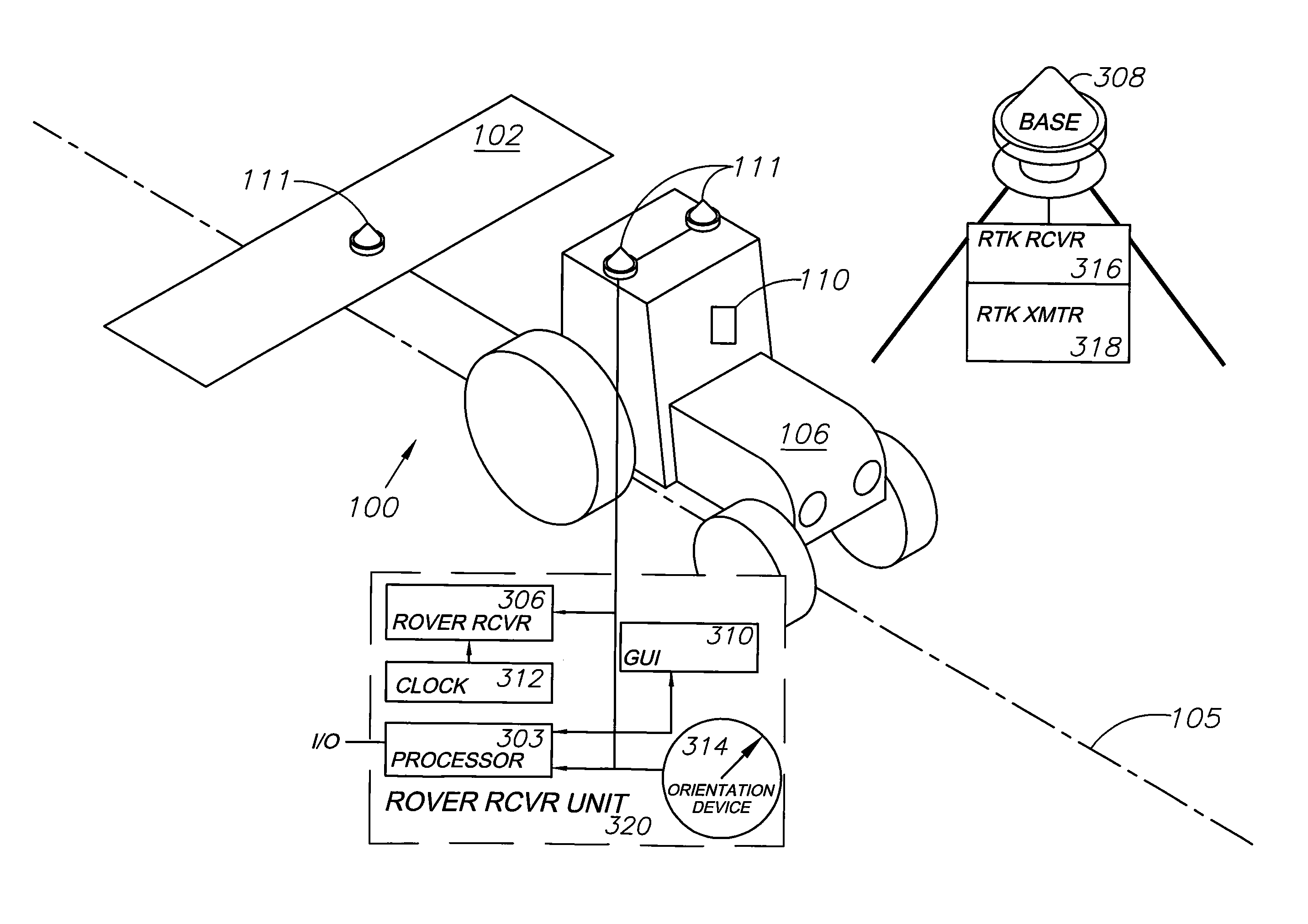
[0038]FIG. 1 shows a sprayer vehicle assembly 100 (hereinafter referred to as “sprayer”) for spraying a crop swath 104. The sprayer 100 includes a vehicle 106 which tracks along the swath 104, and a spray unit 102 fitted to the vehicle 106 and for spraying the swath 104. A control system 110 is provided onboard the vehicle 106 for automatically controlling the position of the sprayer 100 relative to the swath during spraying. The control system 110 can automatically control the steering and speed of the vehicle 106, and also activates the spray unit 102.

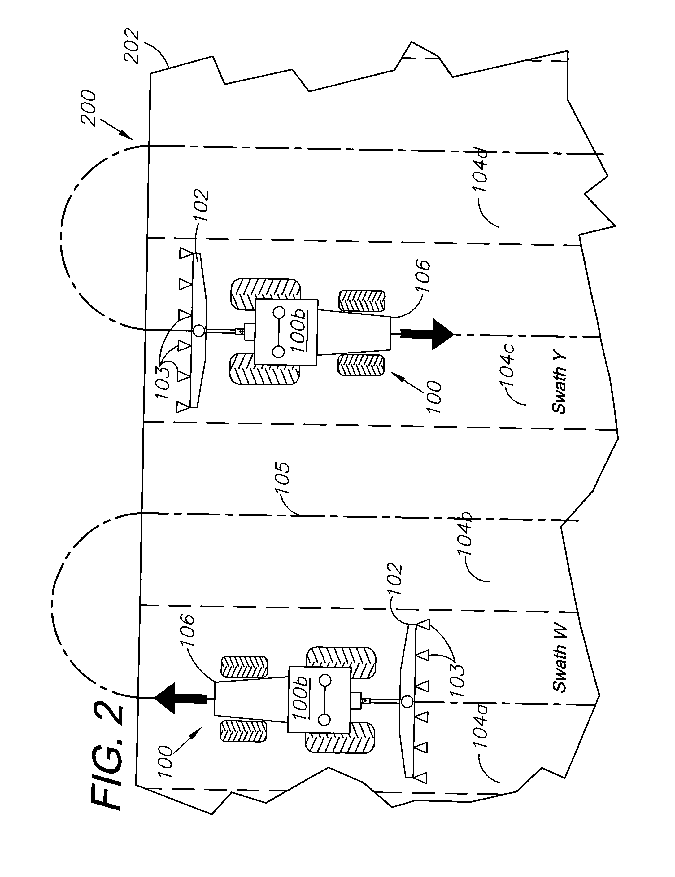
[0039]FIG. 2 shows a spraying system 200 for spraying a field 202. The spraying system 200 includes many like driverless, autonomous sprayers 100 which perform collaborative behaviour to spray the field 202. A command centre 204 places tasks relating to spraying crop swaths 104 of the field 202 within a common database. The database is distributed, with mirrored local versions of the database being located proximal to respective cont...


PUM


Abstract

The present invention relates to a method for controlling vehicle assemblies using respective controllers. Each controller is in communication with a database. Each controller is configured to perform the step of placing a bid in the database in relation to a task to be performed by the vehicle assembly. The controller then determines whether the placed bid was successful and, subsequent to determining that the placed bid was successful, controls the vehicle assembly to perform the task.

Description

CROSS-REFERENCE TO RELATED APPLICATION[0001]This application claims priority in U.S. Provisional Patent Application No. 61 / 265,281, filed Nov. 30, 2009, which is incorporated herein by reference.BACKGROUND[0002]1. Field of the Invention[0003]The present invention generally relates to a method for controlling a vehicle assembly using a controller. The present invention has particular, although not exclusive application to controllers for agricultural vehicle assemblies.[0004]2. Description of the Related Art[0005]The reference to any prior art in this specification is not, and should not be taken as an acknowledgement or any form of suggestion that the prior art forms part of the common general knowledge.[0006]Autonomous or driverless vehicles can perform tasks in hazardous environments and thereby remove the possibility of operators becoming injured or even killed.[0007]Some environments require multiple autonomous vehicles to operate in the same geographic area. Coordinating the ve...

Claims


Application Information

Patent Timeline
IPC IPC(8): G06F7/00G01C21/00
CPCG05D1/0278G05D1/0291G05D1/0088A01B69/008A01B79/005G05D2201/0201
Inventor REEVE, DAVID R.JONES, MALCOLM B.RAMM, ANDREAS F.
Owner AGJUNCTION
Why Eureka
Try Eureka