Magnetocaloric element

a magnetic element and caloric element technology, applied in the field of magnetic caloric element, can solve the problems of limited interest in solving the problem of low magnetocaloric effect of these materials, limit the useful calorific output of these materials, etc., and achieve the effect of speeding up the creation of temperature gradients and quickly reaching established operating rates

Inactive Publication Date: 2011-07-21
COOLTECH APPL S
View PDF5 Cites 93 Cited by
  • Summary
  • Abstract
  • Description
  • Claims
  • Application Information

AI Technical Summary

Benefits of technology

[0010]The goal of the initiating means is to speed up the creation of the temperature gradient between the two opposite ends of the magnetoca...

Problems solved by technology

Its limits in terms of its useful calorific output and its efficiency are also well known.
Now, a particular difficulty consists in producing a magnetocaloric generator that can operate with a high efficiency in a wire temperature range in order to adapt the temperature levels of the generator to the external temperatures.
But the magnetocaloric effect of these materials is low, and this limits the interest of this solution, since it does not allow obtaining an acceptable g...

Method used


Image

  • Magnetocaloric element
  • Magnetocaloric element
  • Magnetocaloric element

Examples


Embodiment Construction

[0035]In the implementation examples shown, the identical parts or sections have the same numerical references.

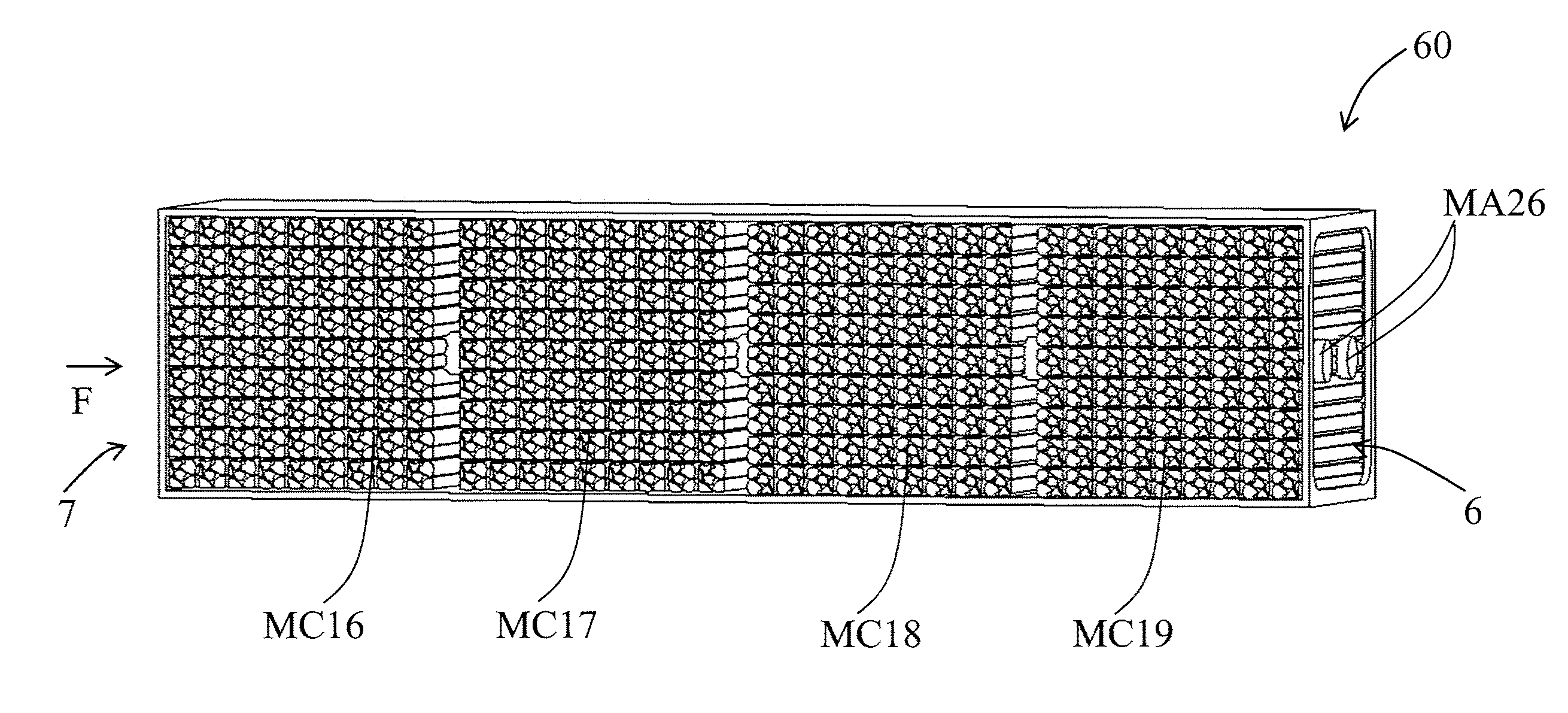
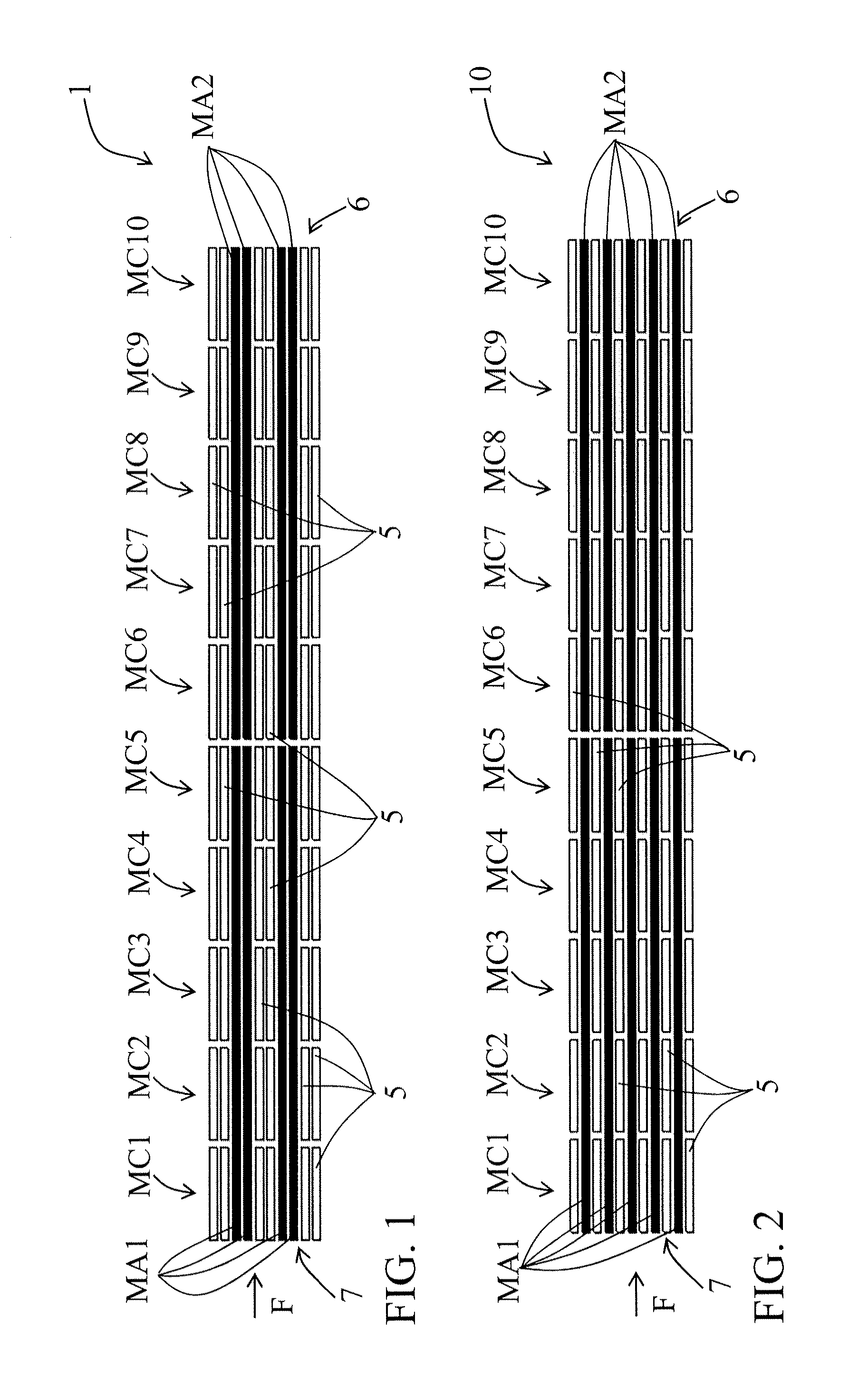
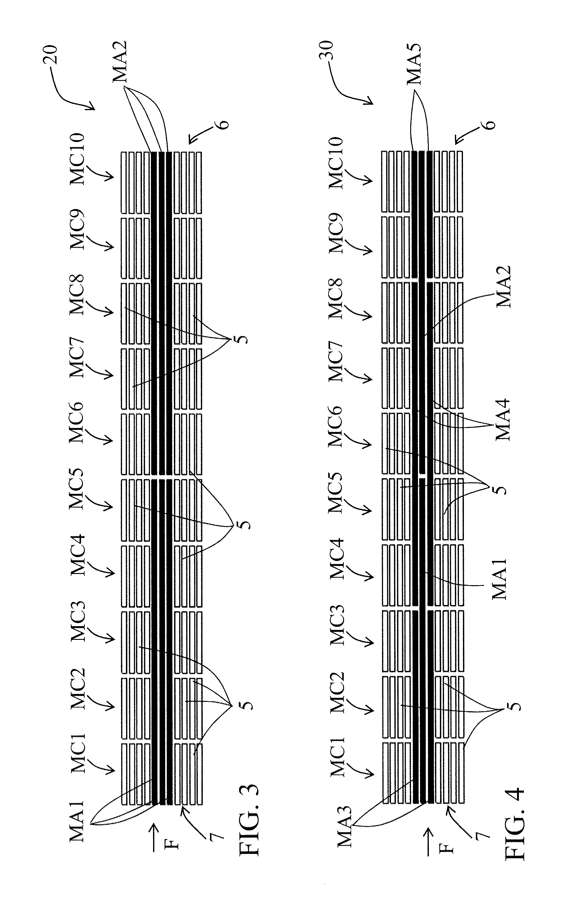
[0036]In reference to FIG. 1, the magnetocaloric element 1 represents a first variant of a first embodiment of the invention and is intended to be integrated in a magnetocaloric heat generator. It is made up of ten sets MC1-10 of small plates 5 of magnetocaloric material. In this first embodiment, each set MC1-10 made out of different magnetocaloric material is made up of an assembly of identical small plates 5.

[0037]In each set MC1-10, these small plates 5 are spaced from each other to allow heat transfer fluid to circulate between two adjacent small plates 5 and to exchange thermal energy with the latter. For that purpose, a spacing or separating device (not represented), which ensures a space for the passage of the heat transfer fluid, can separate the small plates 5 two by two. The fluid circulation direction is represented by arrow F in FIG. 1.

[0038]The sets MC1-10 are...


PUM


Abstract

A magnetocaloric element (1) made by an alignment of at least two adjacent sets (MC1-10) of magnetocaloric materials having different Curie temperatures. The magnetocaloric materials within a same set (MC1-10) have the same Curie temperature. The sets (MC1-10) are arranged according to an increasing Curie temperature, and the magnetocaloric element (1) comprises elements (MA1-2) for initiating a temperature gradient between a hot end (6) and an opposed cold end (7) of the magnetocaloric element (1).

Description

[0001]This application is a National Stage completion of PCT / FR2009 / 001128 filed Sep. 23, 2009, which claims priority from French patent application Ser. No. 08 / 05280 filed Sep. 25, 2008.FIELD OF THE INVENTION[0002]The present invention relates to a magnetocaloric element made of an alignment of at least two adjacent sets of magnetocaloric materials having a different Curie temperature. Such a set is preferably intended for being integrated in a heat generator.BACKGROUND OF THE INVENTION[0003]Magnetic refrigeration technology at ambient temperature has been known for more than twenty years and the advantages it provides in terms of ecology and sustainable development are widely acknowledged. Its limits in terms of its useful calorific output and its efficiency are also well known. Consequently, all the research undertaken in this field tends to improve the performances of such a generator, by adjusting the various parameters, such as the magnetization power, the performances of the ...

Claims


Application Information

Patent Timeline
IPC IPC(8): F25B21/00H01F1/00
CPCF25B21/00Y02B30/66F25B2321/002Y02B30/00
Inventor MULLER, CHRISTIANHEITZLER, JEAN-CLAUDEHAMM, JEAN-LUC
Owner COOLTECH APPL S
Why Eureka
Try Eureka