
Chip package and method for fabricating the same

Active Publication Date: 2011-07-21
XINTEC INC
View PDF3 Cites 17 Cited by
  • Summary
  • Abstract
  • Description
  • Claims
  • Application Information

AI Technical Summary

Benefits of technology

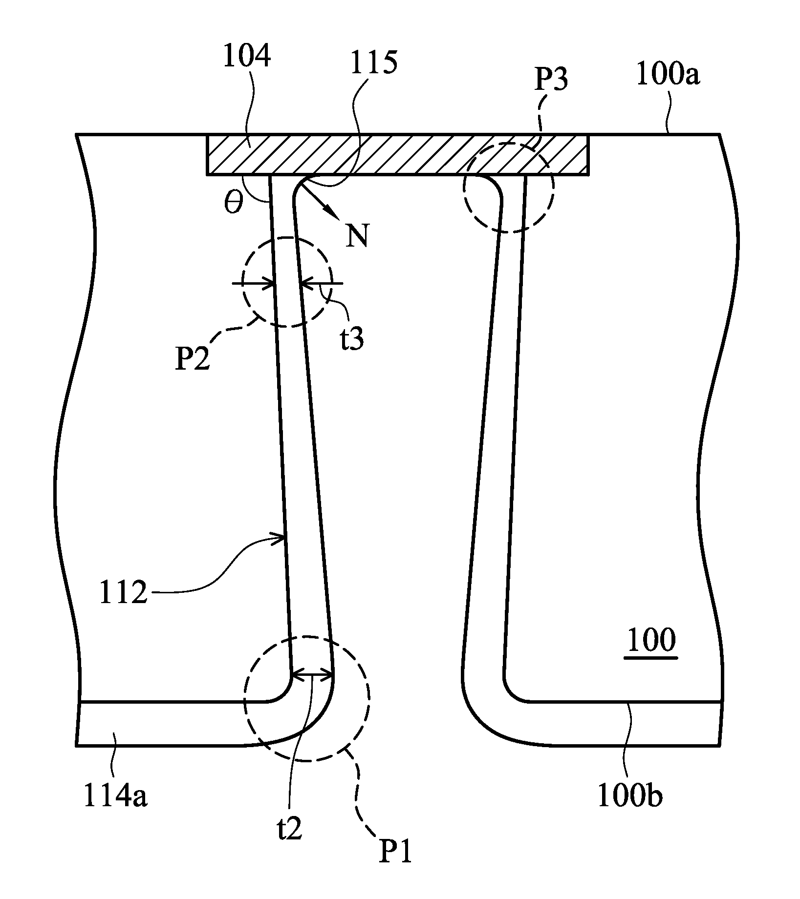
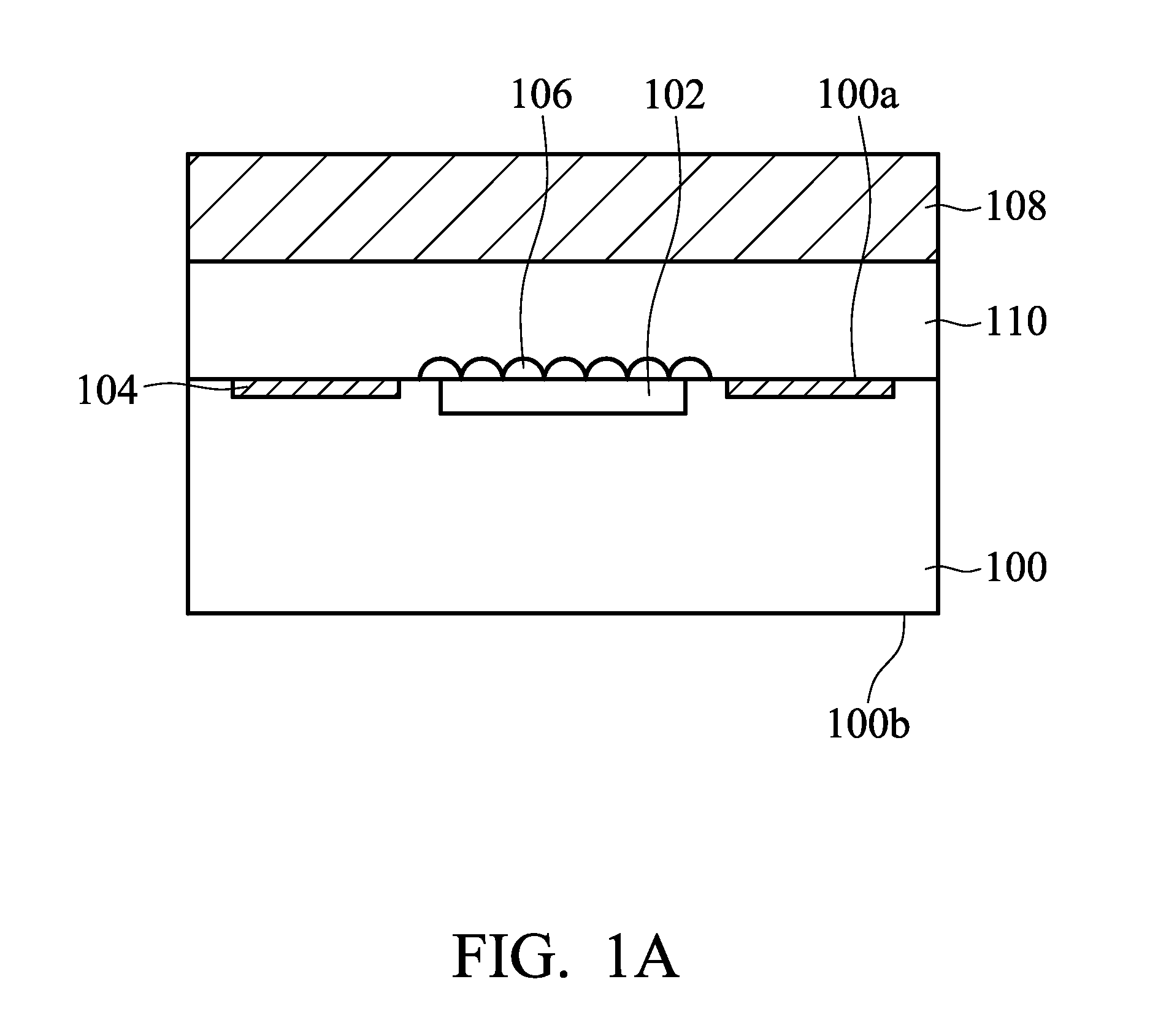
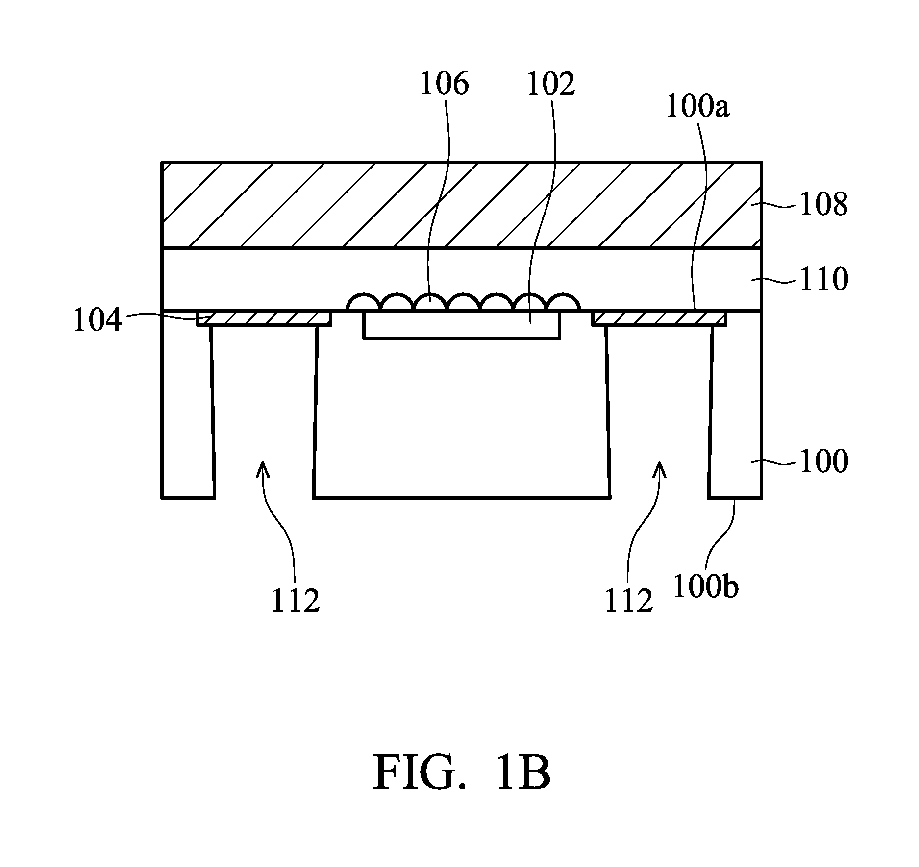
[0008]An embodiment of the present invention provides a method for forming a chip package including providing a substrate having an upper surface and a lower surface, wherein the substrate comprises a chip and a pad therein or thereon and the pad is electrically connected to the chip, removing a portion of the substrate from the lower surface of the substrate to form a hole exposing the pad, wherein a lower opening of the hole near the lower surface has a width that is shorter than that of an upper opening of the hole near the upper surface, forming an insulating layer on a sidewall and a bottom portion of the hole, removing a portion of the insulating layer on the bottom portion of the hole to expose a portion of the pad, and forming a conducting layer on the sidewall and the bottom portion of the hole, wherein the conducting layer electrically contacts the pad.
[0032]The removable adhesive and the temporary substrate are used in an embodiment of the invention such that the packaging process of the chip may be performed smoothly. After the adhesive and the temporary substrate are removed, light may be received or emitted more successfully by the chip package. Due to the fabricating process of the hole having the conical or pyramidical profile with steep sidewall, no additional photolithography process is needed when the opening of the insulating layer exposing the pad is formed. Fabrication cost and time may be significantly reduced. Also, damage of material layers in the chip package may be prevented, which effectively improves yield and reliability of the chip package.

Problems solved by technology

For a chip package, such as a light detecting chip package or a light emitting chip package, light receiving and emitting are often negatively affected by a medium thereof (such as a glass).

Method used


Image

  • Chip package and method for fabricating the same
  • Chip package and method for fabricating the same
  • Chip package and method for fabricating the same

Examples


Embodiment Construction

[0014]The following description is of the best-contemplated mode of carrying out the invention. This description is made for the purpose of illustrating the general principles of the invention and should not be taken in a limiting sense. The scope of the invention is best determined by reference to the appended claims.

[0015]It is understood, that the following disclosure provides many different embodiments, or examples, for implementing different features of the invention. Specific examples of components and arrangements are described below to simplify the present disclosure. These are, of course, merely examples and are not intended to be limiting. In addition, the present disclosure may repeat reference numbers and / or letters in the various examples. This repetition is for the purpose of simplicity and clarity and does not in itself dictate a relationship between the various embodiments and / or configurations discussed. Furthermore, descriptions of a first layer “on,”“overlying,” (...


PUM


Abstract

An embodiment of the invention provides a chip package, which includes a substrate having an upper surface and a lower surface, a chip disposed in or on the substrate, a pad disposed in or on the substrate and electrically connected to the chip, a hole extending from the lower surface toward the upper surface, exposing the pad, wherein a lower opening of the hole near the lower surface has a width that is shorter than that of an upper opening of the hole near the upper surface, an insulating layer located overlying a sidewall of the hole, and a conducting layer located overlying the insulating layer and electrically connected to the pad.

Description

CROSS REFERENCE[0001]This Application claims the benefit of U.S. Provisional Application No. 61 / 296,857, filed on Jan. 20, 2010, the entirety of which is incorporated by reference herein.BACKGROUND OF THE INVENTION[0002]1. Field of the Invention[0003]The present invention relates to a chip package and a fabrication method thereof, and in particular relates to a chip package having a through substrate via and a fabrication method thereof.[0004]2. Description of the Related Art[0005]For a chip package, such as a light detecting chip package or a light emitting chip package, light receiving and emitting are often negatively affected by a medium thereof (such as a glass). In addition, reliability of the chip package may often be affected by stress thereto. Also, when fabricating a chip package, a complicated patterning process is often needed, which increases fabrication costs.[0006]Therefore, a chip packaging technique to reduce or solve the problems mentioned above is desired.BRIEF SU...

Claims


Application Information

Patent Timeline
IPC IPC(8): H01L23/48H01L21/44
CPCH01L21/76898H01L23/481H01L23/147H01L23/49827H01L27/14618H01L2224/02372H01L2224/05548H01L2924/1461H01L2224/06181H01L2224/13022H01L2224/13024H01L2224/0401H01L2924/00
Inventor LOU, BAI-YAOLIU, TSANG-YUYEOU, LONG-SHENG
Owner XINTEC INC
Learn More