
Method for forming a pattern of a semiconductor device

a technology of semiconductor devices and fine patterns, which is applied in the direction of semiconductor devices, basic electric elements, electrical appliances, etc., can solve the problems of deterioration of dummy patterns, difficult to form fine patterns having a small cd, and difficulty in forming fine patterns with a short wavelength. achieve the effect of improving yield and reliability of semiconductor devices

Active Publication Date: 2009-04-02
SK HYNIX INC
View PDF4 Cites 18 Cited by
  • Summary
  • Abstract
  • Description
  • Claims
  • Application Information

AI Technical Summary

Benefits of technology

The present invention provides a method for forming a fine pattern in a semiconductor device using a spacer. This method improves the yield and reliability of the semiconductor device. The method involves forming a sacrificial pattern, removing the sacrificial pattern to form a spacer, and then patterning the underlying layer in the cell region and the peripheral circuit region with the spacer pattern and a photoresist pattern to obtain the fine pattern. An alignment key or an overlay vernier pattern is formed when forming the spacer pattern. The mask pattern defines a dummy pattern for forming a pad in an outer region of the spacer pattern. The method also involves etching the sacrificial pattern and the etching barrier film using the spacer pattern and the photoresist pattern as a mask. The technical effects of this invention are improved yield and reliability of the semiconductor device through the use of a spacer and improved patterning accuracy.

Problems solved by technology

A new photoresist material having a high reactivity to short wavelengths is required with an exposer using the short wavelengths, so that it is difficult to form a fine pattern having a CD less than a short wavelength.
As mentioned above, in the conventional method for forming a fine pattern of a semiconductor device, it is difficult to form a fine pattern having a small CD due to limits of the resolution of the exposer.
As a result, the dummy pattern is deteriorated, and yield and reliability of the semiconductor device is degraded.

Method used


Image

  • Method for forming a pattern of a semiconductor device
  • Method for forming a pattern of a semiconductor device
  • Method for forming a pattern of a semiconductor device

Examples


first embodiment

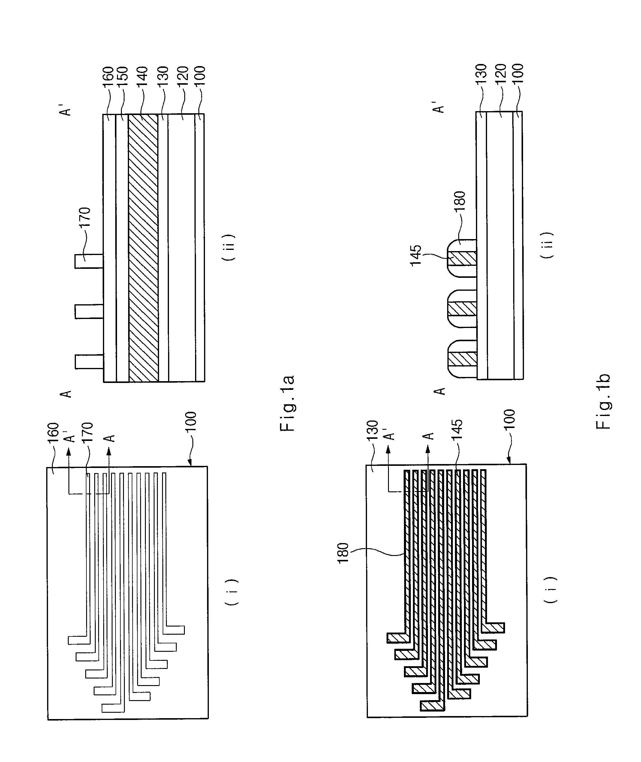
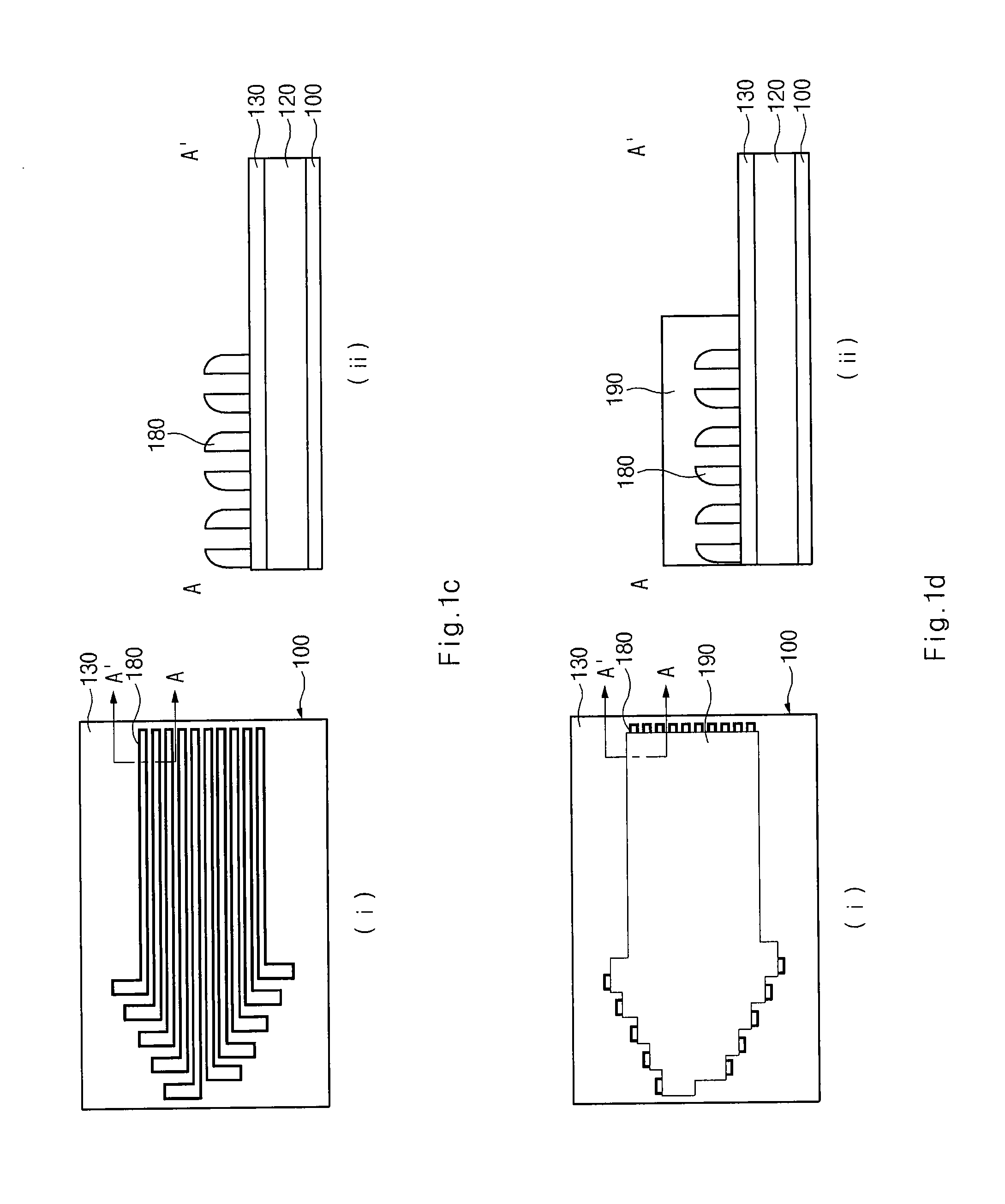
[0035]FIGS. 3a and 3b are cross-sectional diagrams illustrating a dummy pattern according to the present invention. FIG. 3a shows a process for forming a dummy pattern 200a that defines a pad in a peripheral circuit region after the processes of FIG. 1a to 1e are performed in the cell region.

[0036]Referring to FIG. 3a, a photoresist pattern 200a that defines a dummy pattern for a pad is formed over an etching barrier film 330 including an alignment key pattern 175a in a peripheral circuit region.

[0037]Referring to FIG. 3b, the etching barrier film 330 and a first hard mask layer 320 are etched using the alignment key pattern 175a and the photoresist pattern 200a as a mask to form a first hard mask pattern (not shown). Then a semiconductor substrate 300 is etched using the first hard mask pattern as a mask to form a dummy pattern 315 and an alignment key 325.

second embodiment

[0038]FIGS. 4a and 4b are cross-sectional diagrams illustrating a dummy pattern according to the present invention. Like FIG. 3a, FIG. 4a shows a process for forming a dummy pattern 200b that defines a pad in a peripheral circuit region after the processes of FIG. 1a to 1e are performed in the cell region.

[0039]Referring to FIG. 4a, a photoresist pattern 200b that defines a dummy pattern 415 for a pad is formed over an etching barrier film 430 including an alignment key pattern 175a in a peripheral circuit region.

[0040]Referring to FIG. 4b, the etching barrier film 430 and a first hard mask layer 420 are etched using the alignment key pattern 175a and the photoresist pattern 200b as a mask to form a first hard mask pattern (not shown) similarly to the process shown in FIG. 3b. Then a semiconductor substrate 400 is etched using the first hard mask pattern (not shown) as a mask to form a dummy pattern 415 and an alignment key 425.

[0041]In the embodiments shown in FIGS. 3a, 3b and FIGS...


PUM


Abstract

In a method for forming a fine pattern of a semiconductor device, forming a spacer for double patterning of a cell region is performed separate from forming a mask pattern that defines a dummy pattern for a pad of a peripheral circuit region.

Description

CROSS-REFERENCES TO RELATED APPLICATIONS[0001]Priority is claimed to Korean patent application number 10-2007-0098451, filed on Sep. 28, 2007, and Korean patent application number 10-2008-0060486, filed on Jun. 25, 2008, which is incorporated by reference in its entirety.BACKGROUND OF THE INVENTION[0002]The present invention relates to a method for forming a fine pattern of a semiconductor device, and more specifically, to preventing a defect generated from first and second mask processes in a double exposure process to overcome a resolution limit of an exposer.[0003]As semiconductor devices become smaller and more highly-integrated, the chip area is increased in proportion to an increase of memory capacity, but an area of a cell region where a pattern of the semiconductor device is formed is decreased. Since more patterns are required in a limited cell region in order to secure a desired memory capacity, a critical dimension (CD) of the pattern is decreased so that the pattern beco...

Claims


Application Information

Patent Timeline
Patent Type & Authority Applications(United States)
IPC IPC(8): H01L21/302
CPCH01L21/0337H01L21/0338H01L27/1052H01L27/105H01L21/32139H10B12/50
Inventor BAN, KEUN DO
Owner SK HYNIX INC
Learn More