Multidirectional light emitting fixture

Inactive Publication Date: 2011-07-21
HARRIS WILLIAM F
View PDF3 Cites 11 Cited by
  • Summary
  • Abstract
  • Description
  • Claims
  • Application Information

AI Technical Summary

Benefits of technology

[0009]The angling of an extended member creates a concave face and a convex face of each extended member and the hub. The concave face of the extended member and the hub is the interior face (relative to the angling direction of the extended member(s) nearest the hub), while the convex face is the exterior face of the extended members and the hub (again, relative to the direction of the angling nearest the hub). The light emitting devices can be configured to shine in a direction generally outward from either the convex or concave face of an extended member and / or the hub. As such, the light fixture can point one or more light emitting devices in different directions, thereby providing multidirectional, three-dimensional illumination.
[0013]In some embodiments, the light fixture, or portions thereof (e.g., extended members and / or hub), can comprise a thermally conductive material. The thermally conductive material can assist in dissipating the heat generated by light emitting devices.

Problems solved by technology

In other illumination applications, such as in airplane cargo bays or crawl spaces under homes, traditional hand held lights are less than optimal.

Method used


Image

  • Multidirectional light emitting fixture
  • Multidirectional light emitting fixture
  • Multidirectional light emitting fixture

Examples


Embodiment Construction

[0025]Embodiments of the present disclosure now will be described more fully hereinafter with reference to the accompanying drawings, in which some, but not all embodiments of the inventions are shown. Indeed, aspects of this disclosure may be embodied in many different forms and should not be construed as limited to the embodiments set forth herein; rather, these embodiments are provided so that this disclosure will satisfy applicable legal requirements. Like numbers refer to like elements throughout.

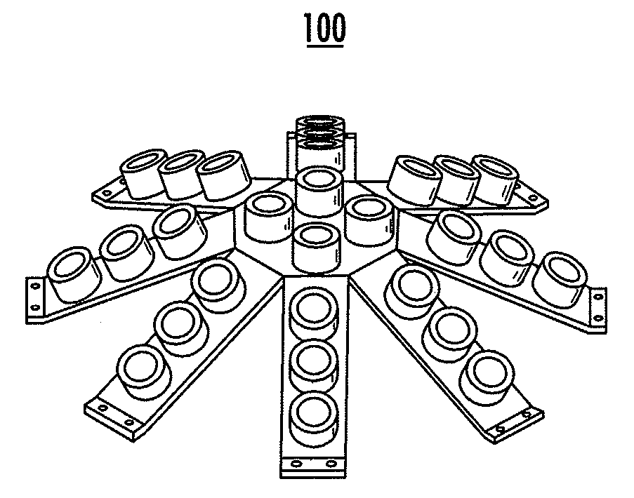
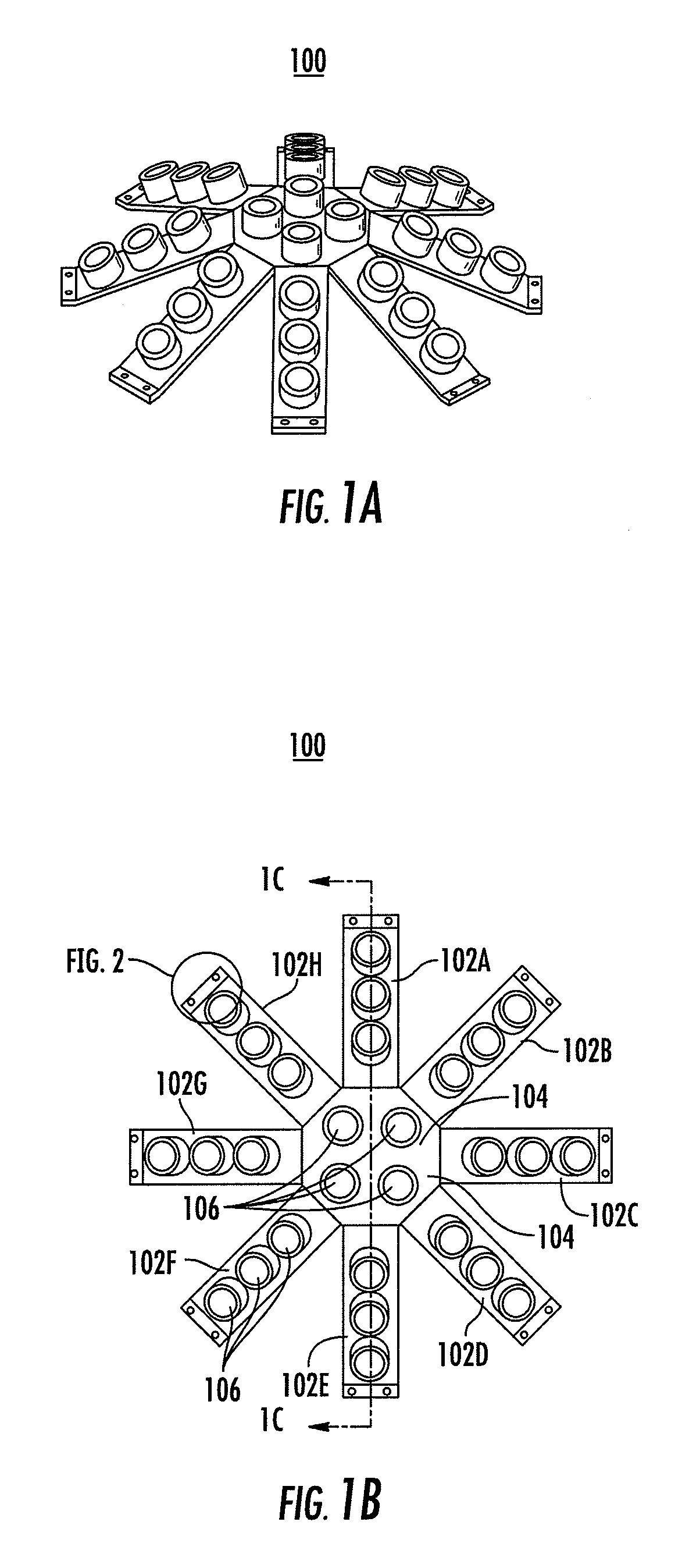
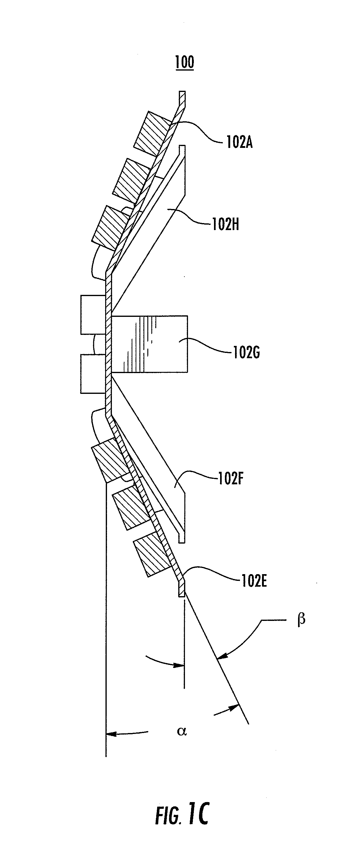
[0026]Discussed herein are embodiments of a lighting fixture having a plurality of physical components, including extended members, that converge at a hub. The hub and / or extended members can be configured to each support one or more light emitting devices. In some embodiments, the electrical components, which provide power to light emitting device(s), can also be configured to meet at the hub.

[0027]The size (e.g., length, width and / or thickness) of the extended members and hub can be ...


PUM


Abstract

Lighting fixtures, apparatuses, methods, systems, computer readable media and other means are provided for a scalable light fixture design that allows a lighting manufacture to easily create custom multidirectional lighting fixtures. The approach may be easily modified and adjusted without departing from the general design and without incurring the otherwise larger redesigning costs often associated with the creation of light fixtures customized for a particular lighting design application.

Description

TECHNOLOGICAL FIELD[0001]Embodiments of the present disclosure relate generally to light emitting fixtures and, more particularly, a light fixture design that can be adjusted for various lighting applications to provide multidirectional, three-dimensional illumination.BACKGROUND[0002]Lighting fixtures are commonly used to support and power light emitting devices, which include various types of light bulbs and light emitting diodes (LEDs). The lighting fixtures and / or the light emitting devices sometimes have a lens or other transparent cover that diffuses the light in multiple directions or focuses the light to a particular area. For example, a parking lot or street lamp may include a diffusion lens that causes the light to scatter and uniformly illuminate a wide area, where as a flash light can have a lens that focuses the light in a given direction.[0003]Some areas require a particular quantity of light, usually measured in lumens, for safety, aesthetic or other reasons. For examp...

Claims


Application Information

Patent Timeline
IPC IPC(8): H05B37/02F21S4/00
CPCF21K9/00F21V23/003F21V23/06F21S9/00F21Y2113/005F21Y2115/10F21Y2113/13
Inventor HARRIS, WILLIAM F.
Owner HARRIS WILLIAM F
Why Eureka
Try Eureka