Method of producing pattern-formed structure and photomask used in the same
Inactive Publication Date: 2005-01-27
DAI NIPPON PRINTING CO LTD
View PDF10 Cites 4 Cited by
Summary
Abstract
Description
Claims
Application Information
AI Technical Summary
This helps you quickly interpret patents by identifying the three key elements:
Problems solved by technology
Method used
Benefits of technology
Benefits of technology
According to the present invention, a pattern having various properties can be formed in a highly precise manner, without necessity of any specific treatment after irradiation of energy. Further, as the photocatalyst-containing-layer side substrate is removed form the pattern-formed structure after irradiation of energy, the pattern-formed structure itself includes no photocatalyst-containing layer, whereby there is no possibility that the pattern-formed structure deteriorates as time elapses by the action of the photocatalyst. Yet further, in the present invention, as the gap or space between the photocatalyst-containing layer and the characteristic-modifiable layer is set within the above-described range, a pattern-formed structure having a pattern produced as a result of modification of characteristic thereof can be obtained in an efficient and highly precise manner.
According to the present invention, patterns having various characteristics can be formed in a highly precise manner, without necessity to carry out any specific post-treatment after energy irradiation. Further, as the photocatalyst-containing-layer side substrate is removed from the pattern-formed structure after energy irradiation, the pattern-formed structure itself is free of the photocatalyst-containing layer. Accordingly, there is no concern that the pattern-formed structure deteriorates as time elapses due to the action of the photocatalyst. Yet further, as the gap between the photocatalyst-containing layer and the characteristic-modifiable layer is set within the above-mentioned range, there is achieved an excellent effect that a pattern-formed structure, having a pattern produced as a result of efficient and excellently precise modification of characteristic thereof, can be obtained.
Problems solved by technology
Therefore, a problem arises, e.g., in that the waste liquid must be properly treated before discarding.
In a case in which a functional substance is used as the photoresist, another problem arisess in that the product deteriorates due to the alkali solution used in the development process.
However, a pattern formed by printing tends to cause a problem in the precision of positioning, whereby highly precise pattern formation is difficult by this method.
However, in such a conventional method of producing a pattern-formed structure by the action of a photocatalyst, the produced pattern-formed structure itself structurally includes the photocatalyst therein, whereby, depending the type of the pattern-formed structure, a problem arises in that the product may deteriorate due to the photocatalyst contained therein.
Method used
Image
Click on the blue label to locate the original text in one second.
Reading with bidirectional positioning of images and text.
Examples
third embodiment
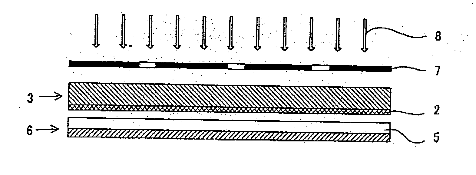
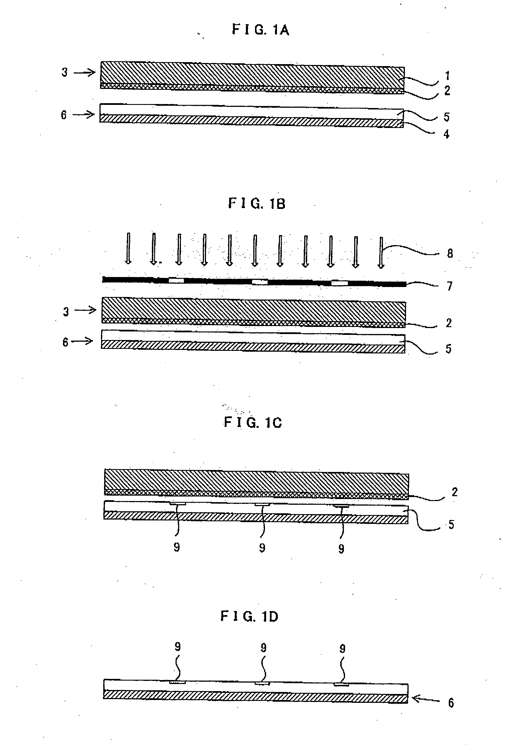
In the above-mentioned description, two cases i.e., the case in which the light-shielding portion is provided between the base material and the photocatalyst-containing layer and the case in which the light-shielding portion is provided on the photocatalyst-containing layer, have been explained regarding the position at which the light-shielding portion is formed. However, another embodiment, in which the light-shielding portion is provided on the surface of the base material at which the photocatalyst-containing layer has not been formed, can also be employed. In this third embodiment, for example, a photomask may be closely but removably attached to the surface. This structure can be preferably employed when the pattern-formed structure is modified in a small lot.
(Primer Layer)
In the present invention, in the case in which the photocatalyst-containing-layer side substrate includes a base material, a light-shielding portion formed in a pattern-like configuration on the base mate...
first embodiment
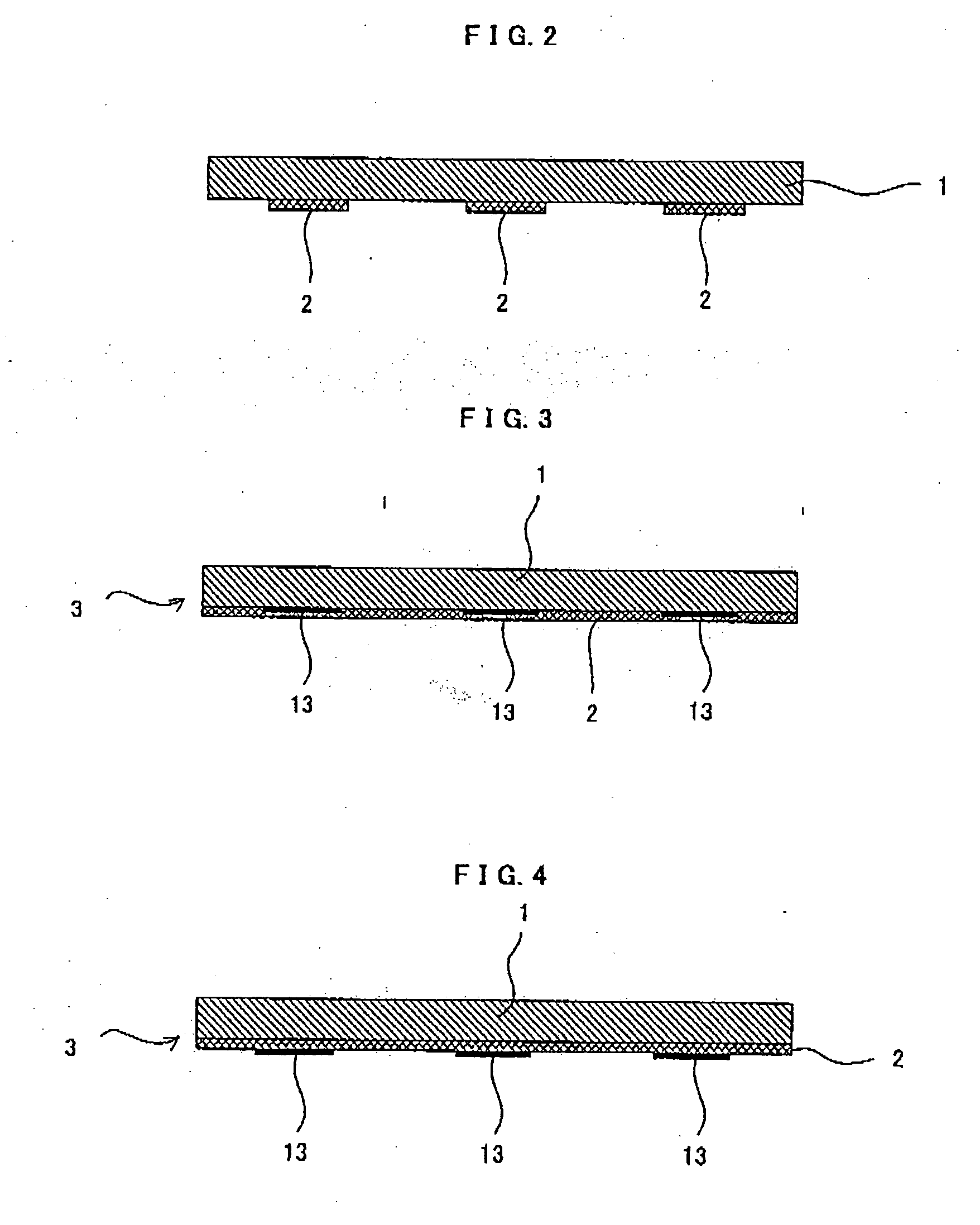
A photomask of the first embodiment includes a transparent base material, a light-shielding portion pattern having thickness of 0.2 to 10 μm and formed, in a pattern-like configuration, on the transparent base material, and a photocatalyst-containing layer formed on the transparent base material and the light-shielding portion pattern. A specific example thereof is shown in FIG. 3.
In short, in the method of producing a pattern-formed structure of the present invention, the photocatalyst-containing-layer side substrate which includes the light-shielding portion can be used as a photomask, due to the functional feature thereof.
second embodiment
A photomask of the second embodiment includes a transparent base material, a photocatalyst-containing layer formed on the transparent base material, and a light-shielding portion pattern having thickness of 0.2 to 10 μm and formed, in a pattern-like configuration, on a photocatalyst-containing layer. A specific example thereof is shown in FIG. 4.
A photomask of the third embodiment includes a transparent base material, a light-shielding portion formed, in a pattern-like configuration, on the transparent base material, a primer layer formed on the transparent base material and the light-shielding portion, and the photocatalyst-containing layer formed on the primer layer. A specific example thereof is shown in FIG. 5.
As each element of any of the above-mentioned photomasks is basically the same as that described in the aforementioned “the method of forming a pattern-formed structure” and the effects achieved by the photomasks of the respective embodiments are basically the same as t...
PUM
Abstract
The present invention discloses a method of producing a pattern-formed structure, comprising the processes of: preparing a substrate for a pattern-formed structure having a characteristic-modifiable layer whose characteristic at a surface thereof can be modified by the action of photocatalyst; preparing a photocatalyst-containing-layer side substrate having a photocatalyst-containing layer formed on a base material, the photocatalyst-containing layer containing photocatalyst; arranging the substrate for a pattern-formed structure and the photocatalyst-containing-layer side substrate such that the characteristic-modifiable layer faces the photocatalyst-containing layer with a clearance of no larger than 200 μm therebetween; and irradiating energy to the characteristic-modifiable layer from a predetermined direction, and modifying characteristic of a surface of the characteristic-modifiable layer, thereby forming a pattern at the characteristic-modifiable layer. According to this method, a highly precise pattern can be formed without necessity to carry out any post-treatment after exposure. Further, there is no concern that the pattern-formed structure itself deteriorates because the produced pattern-formed structure is free of the photocatalyst.
Description
BACKGROUND OF THE INVENTION The present invention relates to a method of producing a pattern-formed structure, which structure is less likely to deteriorate as time elapses after the characteristic thereof is modified by using a photocatalyst, because no pyotocatalyst exists in the resulting pattern-formed structure. The present invention also relates to a photomask which can be used in the aforementioned method of producing a pattern-formed structure. As the conventional method of forming a highly elaborate pattern, is generally known a method of producing a pattern-formed structure by photolithography, such as a method which includes the processes of: carrying out pattern-exposure of a photoresist layer provided by coating on a base material; developing the photoresist after the exposure; and effecting etching of the developed photoresist layer, and a method which includes the processes of: employing a functional substance as the photoresist; and directly forming the aimed patte...
Claims
Application Information
Patent Timeline
Application Date:The date an application was filed.
Publication Date:The date a patent or application was officially published.
First Publication Date:The earliest publication date of a patent with the same application number.
Issue Date:Publication date of the patent grant document.
PCT Entry Date:The Entry date of PCT National Phase.
Estimated Expiry Date:The statutory expiry date of a patent right according to the Patent Law, and it is the longest term of protection that the patent right can achieve without the termination of the patent right due to other reasons(Term extension factor has been taken into account ).
Invalid Date:Actual expiry date is based on effective date or publication date of legal transaction data of invalid patent.

