
Ambulatory device

a technology for ambulatory devices and wheelchairs, applied in the field of medical devices, can solve the problems of difficult operation, bulky wheelchairs, and high cost, and achieve the effects of improving mobility, improving comfort, and improving mobility

Inactive Publication Date: 2011-07-21
BENENATI ANTHONY V
View PDF7 Cites 6 Cited by
  • Summary
  • Abstract
  • Description
  • Claims
  • Application Information

AI Technical Summary

Benefits of technology

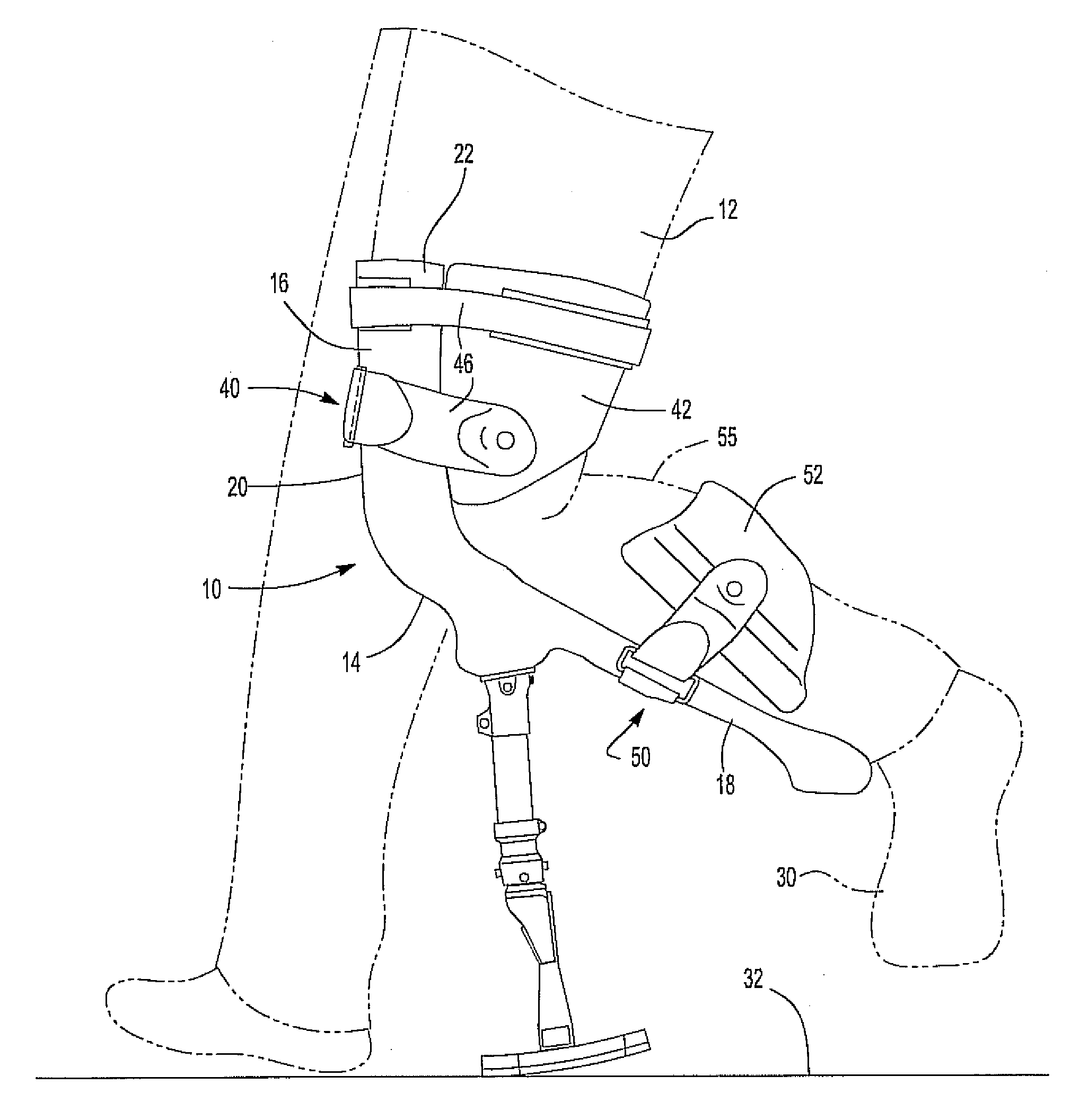
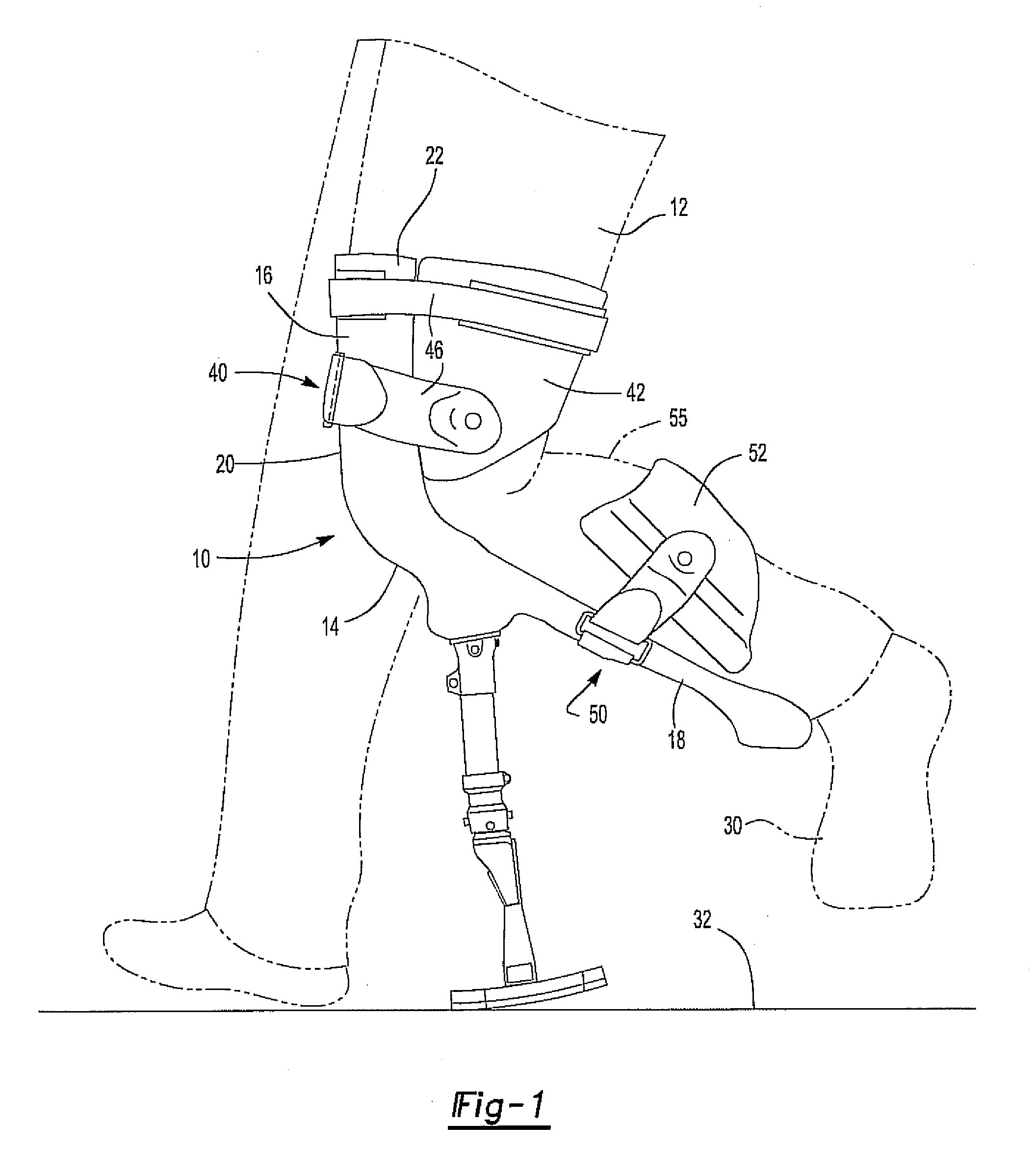
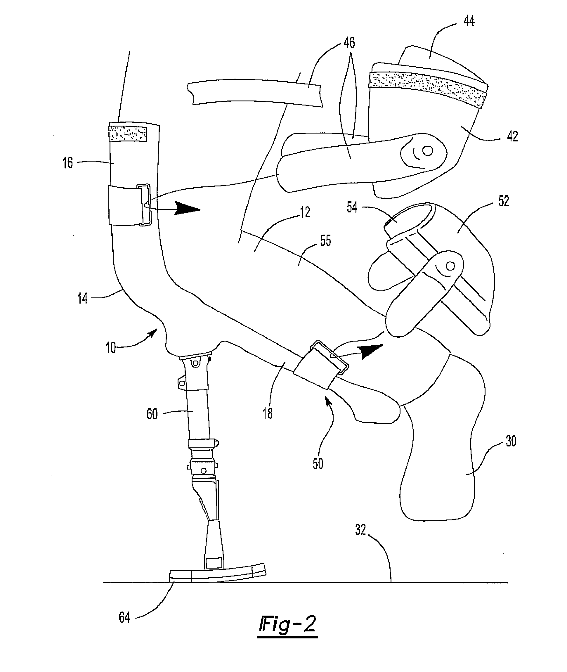
[0010]The thigh support includes a front section adapted to abut against the front of a thigh and spaced apart side sections adapted to abut against the opposite sides of the human thigh. A first fastener having a strap and a thigh pad secures the thigh support to the human thigh so that the thigh support surrounds at least a portion of the thigh and prevents movement between the thigh and the thigh support.
[0013]In use, the ambulatory device is secured to the person's thigh and shin by the first and second straps and their associated thigh and calf pads. In doing so, movement between the ambulatory device and the person's thigh and shin is prevented. This, in turn, provides a stable attachment to the person's leg so that the person may walk in a normal fashion by utilizing the elongated leg and foot plate as an artificial leg while maintaining the person's real foot in an elevated position above the ground support surface.

Problems solved by technology

Such wheelchairs, however, are bulky, expensive, difficult to transport from one location to the other and, for many people, difficult to operate.
Furthermore, many homes are simply not constructed to be wheelchair accessible or wheelchair friendly.
This, in turn, further increases the difficulty of utilizing a wheelchair following foot surgery.
Likewise, treatment of foot and ankle fractures also often require foot off loading.

Method used


Image

  • Ambulatory device
  • Ambulatory device
  • Ambulatory device

Examples


Embodiment Construction

[0019]With reference first to FIGS. 1-3, a preferred embodiment of an ambulatory device 10 in accordance with the present invention is shown attached to the leg 12 of a human. The ambulatory device 10 includes a leg splint 14 having an elongated thigh support 16 and an elongated shin support 18.

[0020]As best shown in FIGS. 1 and 3, the thigh support 16 includes a front section 20 adapted to flatly abut against the front of the thigh of the leg 12 as well as two spaced apart side sections 22. These side sections 22 are adapted to abut against opposite sides of the thigh so that the front of the thigh is at least partially surrounded by the thigh support 16.

[0021]Similarly, the shin support 18 includes a concave surface 24 adapted to abut against the front of the person's shin. The shin support 18, furthermore, extends from the knee 26 to a free end 28 short of the person's ankle.

[0022]The longitudinal axis of the thigh support 16 intersects the longitudinal axis of the shin support 1...


PUM


Abstract

An ambulatory device adapted for attachment to the thigh and shin of a human leg. The ambulatory device includes a leg splint having an elongated thigh support and an elongated shin support extending outwardly from the thigh support at an obtuse angle. The thigh support is constructed of a rigid material and includes a front section adapted to flatly abut against the front of the thigh and spaced apart side sections adapted to abut against opposite sides of the human thigh. A fastener secures the thigh support to the thigh against movement while, similarly, a second fastener secures the shin support to the shin of the leg. An elongated leg has one end attached to and extending perpendicularly outwardly from the shin support while a foot plate is attached to the other end of the leg.

Description

CROSS REFERENCE TO RELATED APPLICATIONS[0001]This application claims priority of U.S. Provisional Patent Application Ser. No. 61 / 295,318 filed Jan. 15, 2010, which is incorporated herein by reference.BACKGROUND OF THE INVENTION[0002]I. Field of the Invention[0003]The present invention relates generally to medical devices and, more particularly, to an ambulatory device.[0004]II. Description of Related Art[0005]Following foot surgery a patient typically cannot place his or her weight on the foot that was the subject of the surgery during the patient's recovery period. This recovery period, moreover, may extend over a period of weeks. Rather, during that recovery period the patient must keep all weight off of the foot in order to allow the foot to heal properly.[0006]Consequently, it has been the prior practice for such patients to confine such patients to wheelchairs during the recovery period. Such wheelchairs, however, are bulky, expensive, difficult to transport from one location t...

Claims


Application Information

Patent Timeline
Patent Type & Authority Applications(United States)
IPC IPC(8): A61H3/00
CPCA61F3/00A61F5/0585A61F5/0195
Inventor BENENATI, ANTHONY V.
Owner BENENATI ANTHONY V
Learn More