
Rotary-rigid orthopaedic rod

a rotary-rigid, orthopaedic rod technology, applied in the field of bone fracture repair equipment and methods, can solve the problems that the plate may not properly address the alignment and stability requirements

Inactive Publication Date: 2011-07-21
CONVENTUS ORTHOPAEDICS INC
View PDF15 Cites 48 Cited by
  • Summary
  • Abstract
  • Description
  • Claims
  • Application Information

AI Technical Summary

Problems solved by technology

Plates may not properly address the alignment and stability requirements for periarticular and intrarticular fractures.

Method used


Image

  • Rotary-rigid orthopaedic rod
  • Rotary-rigid orthopaedic rod
  • Rotary-rigid orthopaedic rod

Examples


Embodiment Construction

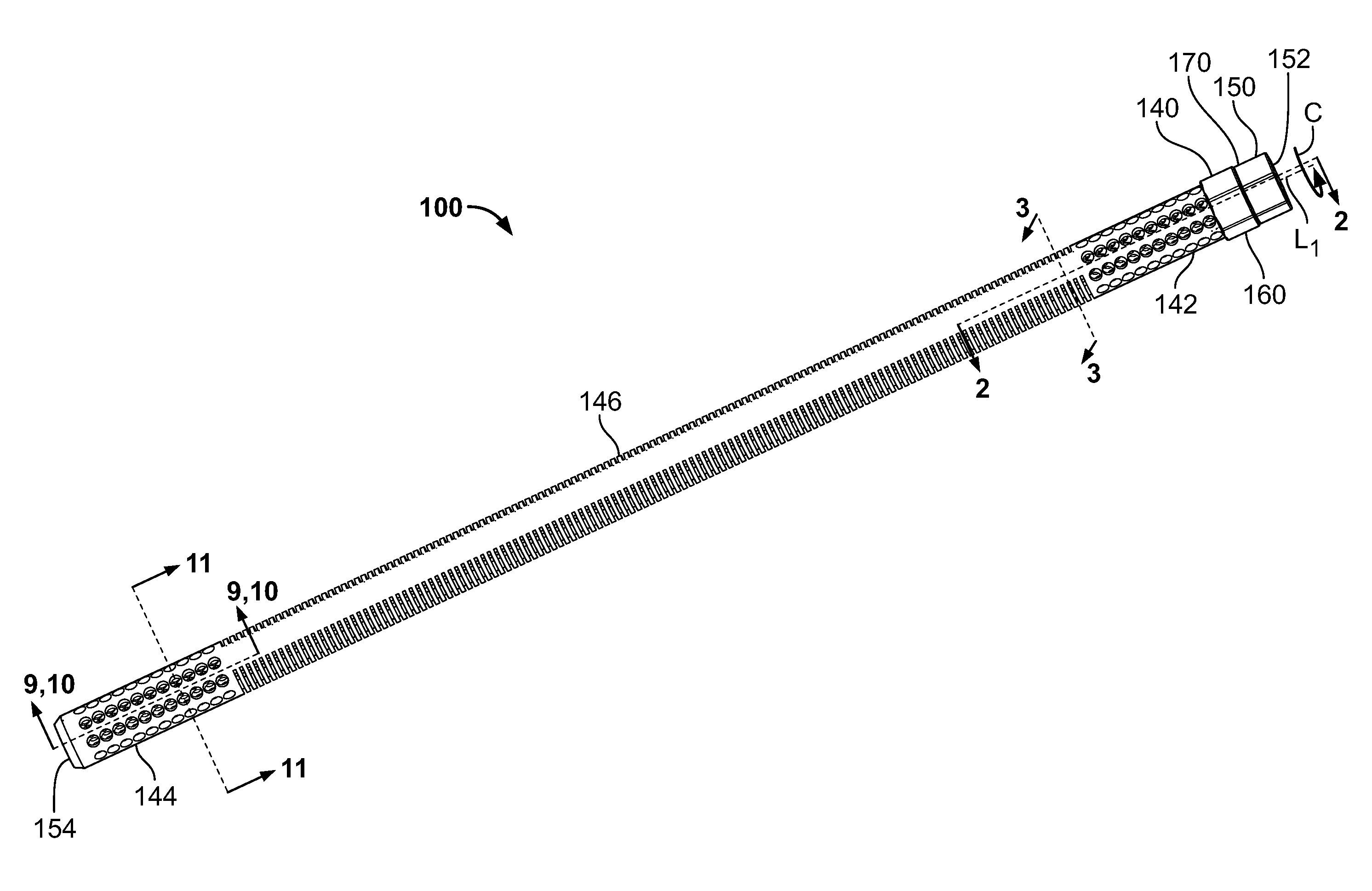
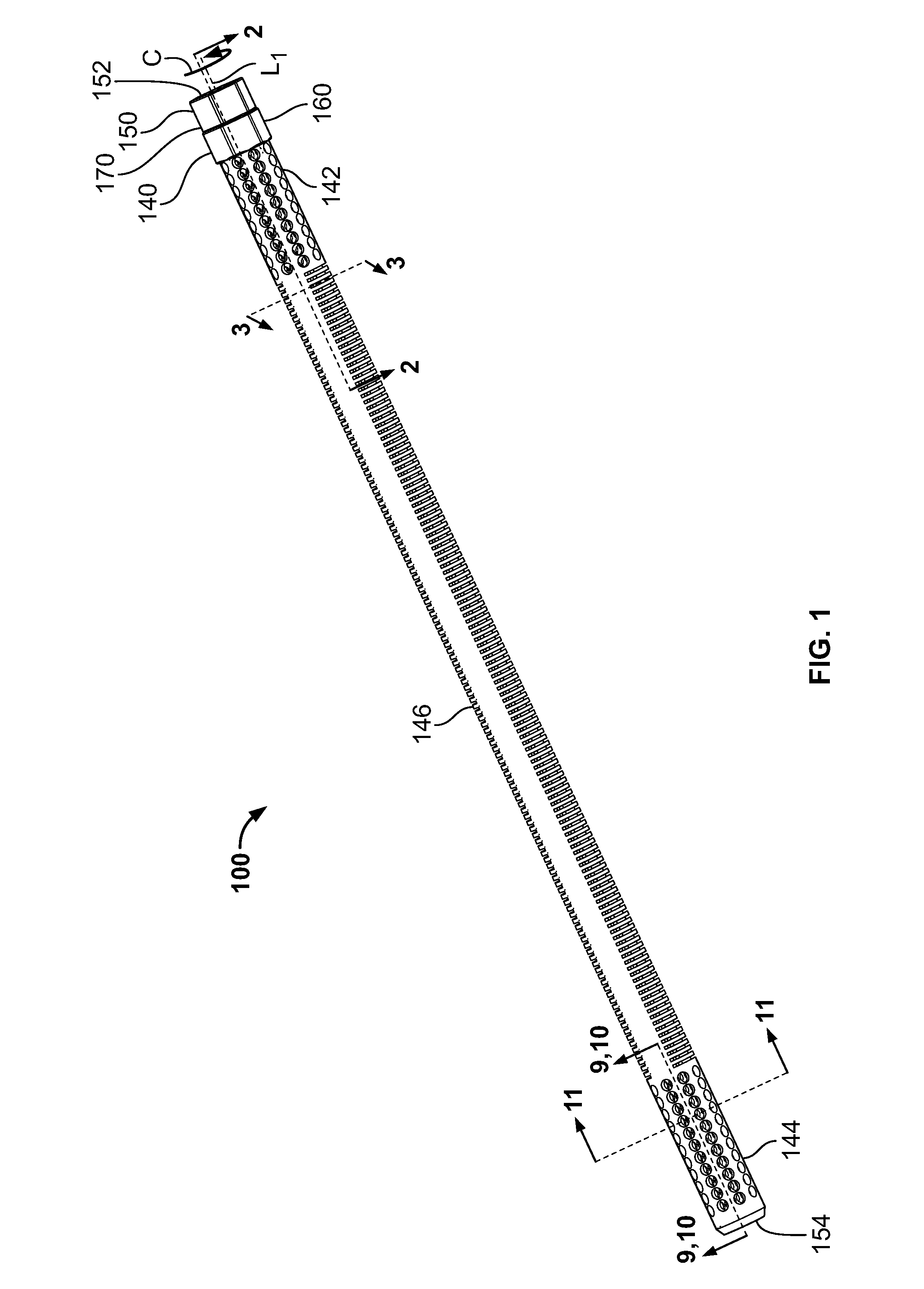
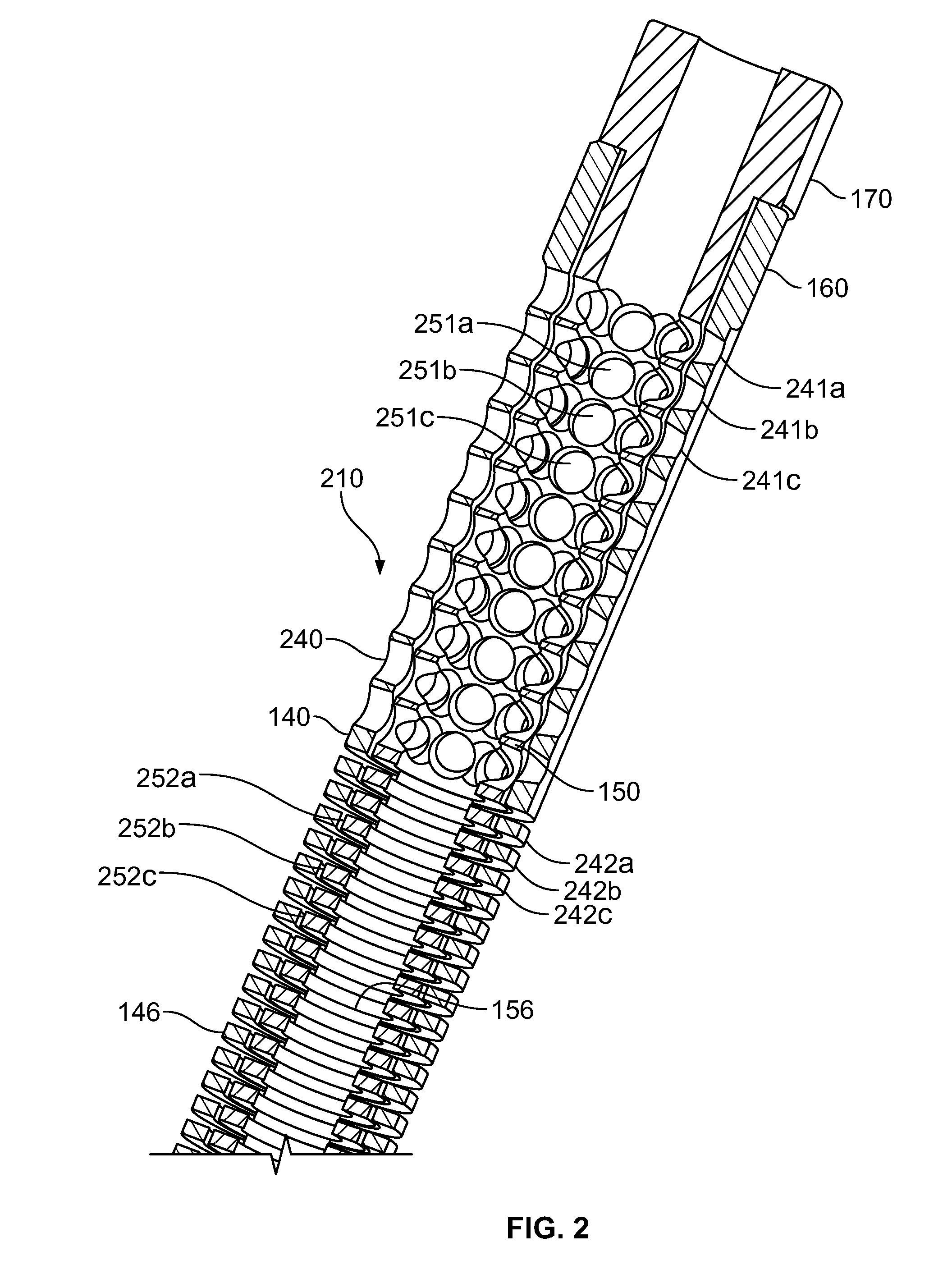
[0034]Apparatus and method for repairing a fractured bone are provided. The apparatus and methods may involve an intramedullary rod. The rod may include a first elongated member and a second elongated member. An elongated member may be referred to herein as a sleeve. Each of the first and second elongated members may be configured to bend in a first direction and to resist bending in a second direction. The first and second elongated members may be arranged such that: (1) the rod is bendable when the first direction of the first elongated member is aligned with the first direction of the second elongated member; and (2) the rod is rigid when the first direction of the first elongated member is aligned with the second direction of the second elongated member.

[0035]An elongated member may be an elongated tubular member. The first elongated member may be disposed coaxially within the second elongated member. The inner member may have a length that is longer, shorter or substantially th...


PUM


Abstract

Apparatus and method for repairing a fractured bone. The apparatus and methods may involve an intramedullary rod. The rod may include a first elongated member and a second elongated member. Each of the first and second elongated members may be configured to bend in a first direction and to resist bending in a second direction. The first and second elongated members may be arranged such that: (1) the rod is bendable when the first direction of the first elongated member is aligned with the first direction of the second elongated member; and (2) the rod is rigid when the first direction of the first elongated member is aligned with the second direction of the second elongated member. Some embodiments may include rods that have sections that may be configured to be curved and rigid.

Description

CROSS-REFERENCE TO RELATED APPLICATIONS[0001]This application is a nonprovisional of U.S. Provisional Applications No. 61 / 295,244, filed on Jan. 15, 2010, which is hereby incorporated by reference in its entirety.FIELD OF TECHNOLOGY[0002]Aspects of the disclosure relate to providing apparatus and methods for repairing bone fractures. In particular, the disclosure relates to apparatus and methods for repairing and / or stabilizing bone fractures utilizing a device that is inserted into a bone.BACKGROUND OF THE INVENTION[0003]Currently, there are many known ways to treat long bone fractures. Common fracture treatments include: (1) nonsurgical immobilization; (2) osteosuture and tension band technologies; (3) percutaneous fixation (e.g., using pins, wires, screws etc.); (4) rigid intramedullary nailing (e.g., using a large rod and external screws); (5) flexible plate osteosynthesis (e.g., a “load sharing” suture); (6) arthroplasty (e.g., using a prosthesis); (7) plating and other indicat...

Claims


Application Information

Patent Timeline
IPC IPC(8): A61B17/58
CPCA61B17/7208A61B17/7283A61B17/7266A61B17/7225A61B17/7258A61B2017/00862A61B2017/00964
Inventor TAYLOR, KYLEHINDRICHS, PAULBRENZEL, MICHAEL P.
Owner CONVENTUS ORTHOPAEDICS INC
Learn More