Nailing device adapted for nail units of different sizes

Active Publication Date: 2011-07-28
APEX MFG
View PDF6 Cites 17 Cited by
  • Summary
  • Abstract
  • Description
  • Claims
  • Application Information

AI Technical Summary

Benefits of technology

[0008]Another main object of the present invention is to provide a nailing device t

Problems solved by technology

Besides, how to push the nail units of different sizes to smoo

Method used


Image

  • Nailing device adapted for nail units of different sizes
  • Nailing device adapted for nail units of different sizes
  • Nailing device adapted for nail units of different sizes

Examples


Example

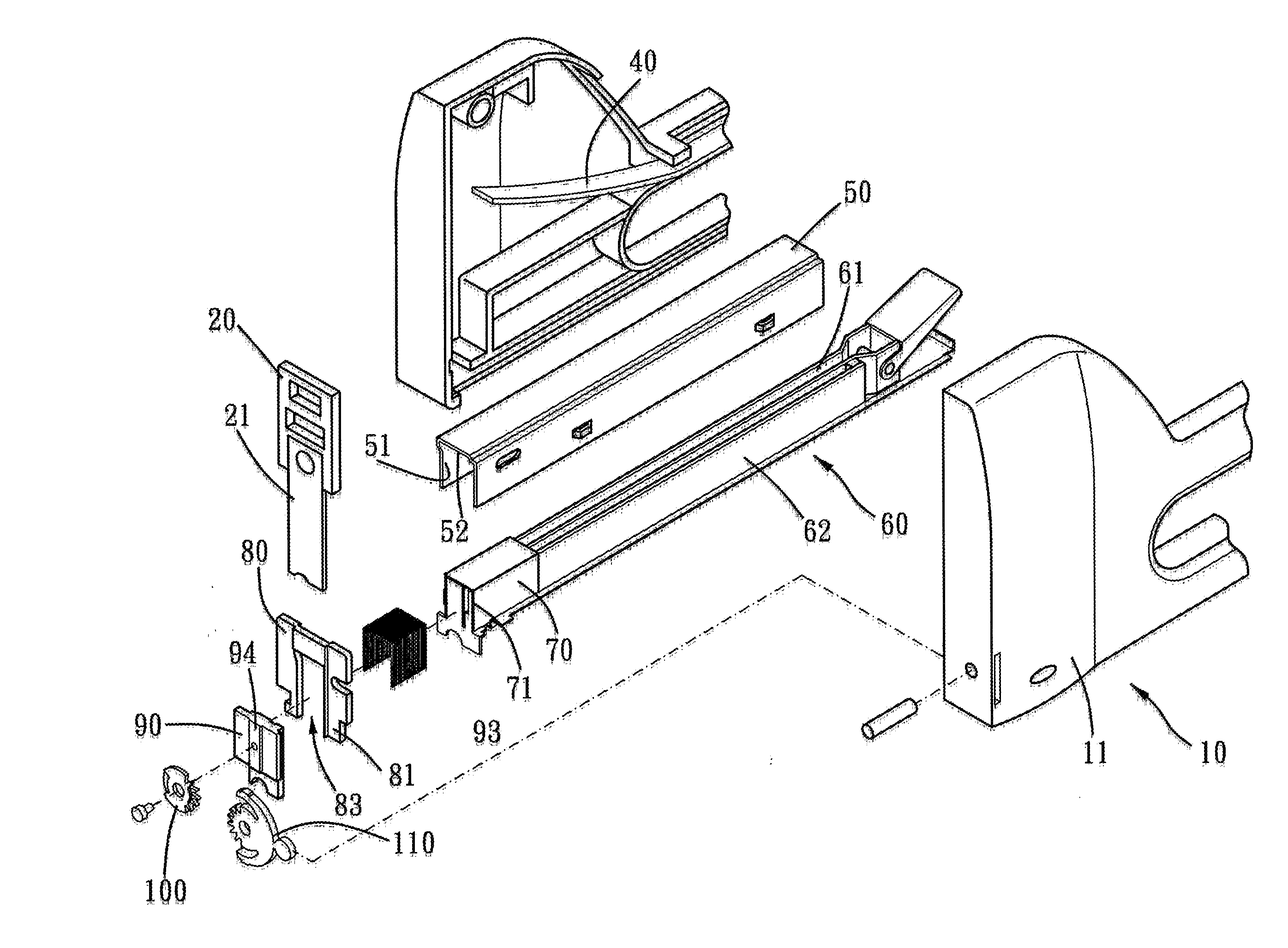
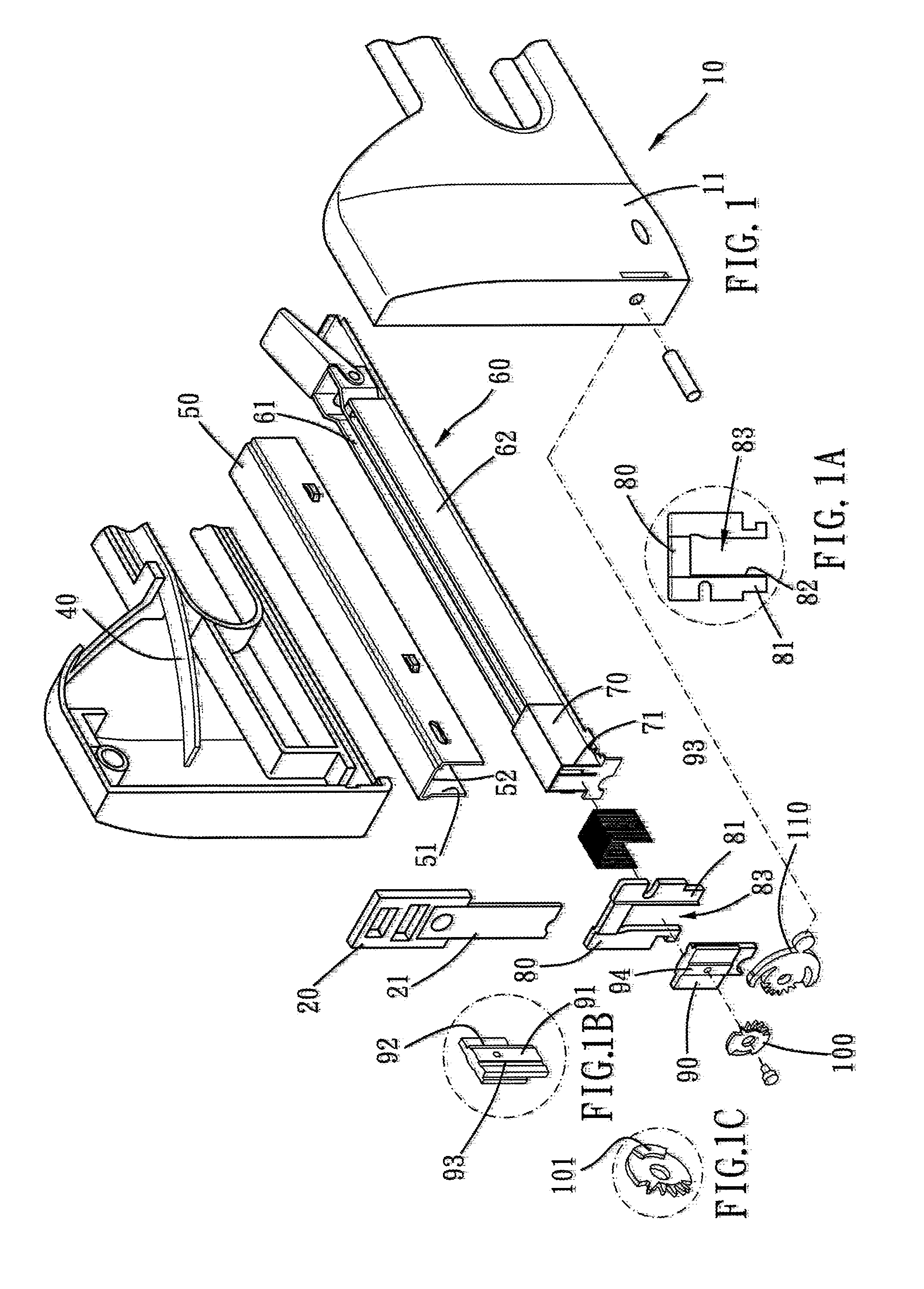
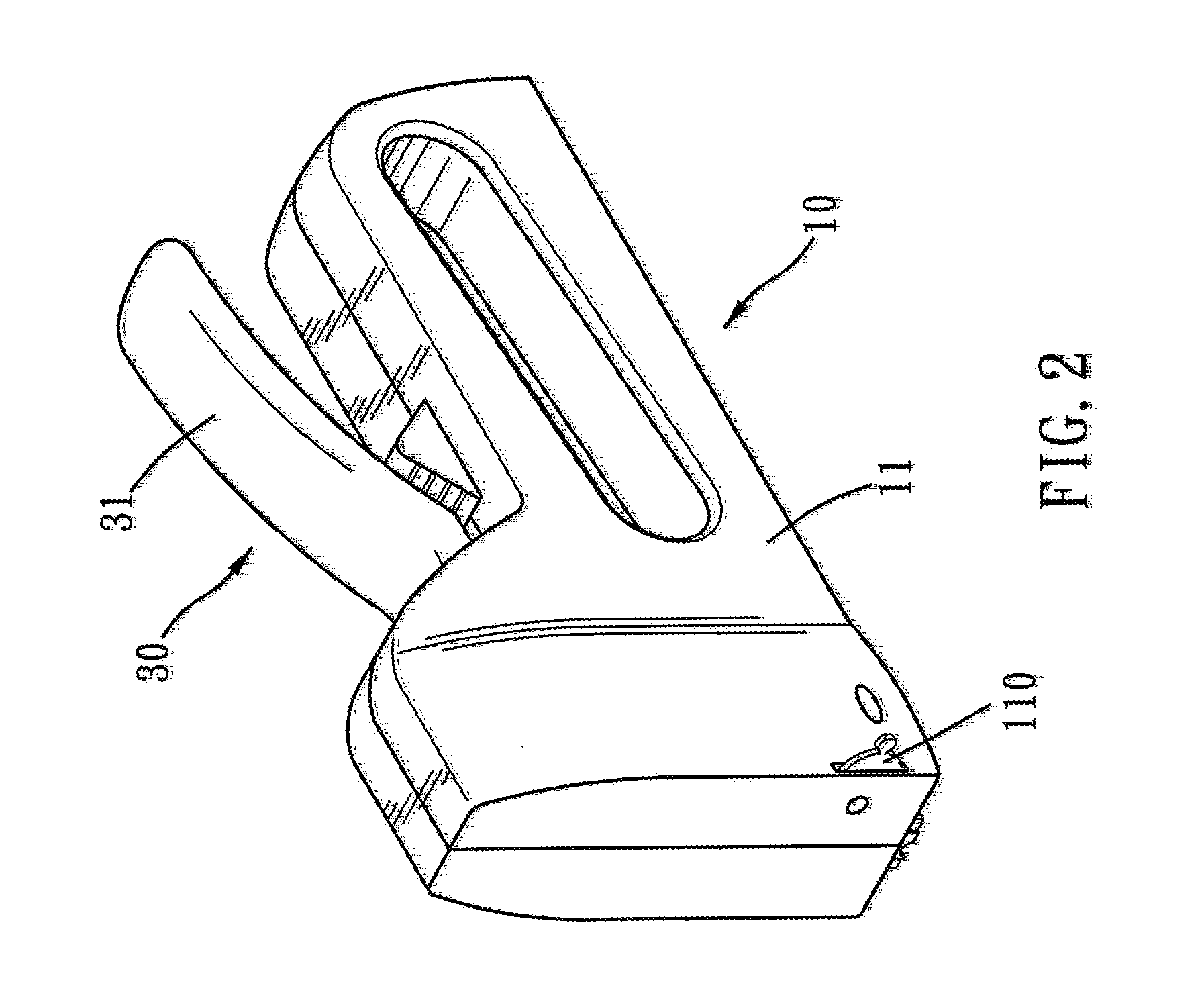
[0030]Please refer to FIG. 1 and FIG. 2 first. In a first embodiment of the present invention, a nailing device includes a main body 10, a striker 20, an actuator 30, a resilient member 40, a nail slot 50, a magazine 60, a nail pusher 70, a guider 80, an adjuster 90 and a controlling means.

[0031]The main body 10 substantially consists of two shells 11 fitted together. A chamber is defined between the shells 11. The main body 10 has a bottom opening communicating with the chamber.

[0032]The striker 20 is disposed in the chamber and is adapted to strike a nail unit out of the chamber. The striker 20 is thus movable between a release position and a potential position. The striker 20 has an abutting surface facing the guider 80.

[0033]The actuator 30 has a pressing portion 31 and a driving portion. The driving portion is inserted into the chamber, and the actuator 30 is adapted to move the striker 20 from the release position to the potential position. More specifically, the driving porti...


PUM


Abstract

A nailing device of the present invention mainly includes a main body, a striker, an actuator, a resilient member, a nail slot, a magazine, a guider, an adjuster and a controlling means. The magazine has a main rail and a sub rail parallel to the main rail, and the main rail is substantially as tall as the sub rail. The adjuster has a protrusive portion having a guiding surface facing the magazine. The guiding surface is vertically formed with two parallel longitudinal grooves and has a bottom end. The longitudinal grooves extend toward the bottom end. The controlling means is for selectively pushing the adjuster to flush the guiding surface with a step surface of the guider.

Description

BACKGROUND OF THE INVENTION[0001]1. Field of the Invention[0002]The present invention relates to a mechanical nailing device, and more particularly to a nailing device adapted for nail units of different sizes.[0003]2. Description of the Prior Art[0004]A nailing device is mainly used to strike a nail into an object, and commonly includes a main body, an actuator, a striker and a magazine. A user of the nailing device can presses the actuator to lift the striker, thereafter the striker can rebound quickly to strike one of the nails in the magazine.[0005]However, how to provide a nailing device that is adapted for nail units of different sizes so as to accommodate different situations is still to be solved.[0006]Besides, how to push the nail units of different sizes to smoothly slide along the magazine without jam is still of concern.SUMMARY OF THE INVENTION[0007]The main object of the present invention is to provide a nailing device adapted for nail units of different sizes.[0008]Ano...

Claims


Application Information

Patent Timeline
IPC IPC(8): B25C5/11B25C1/02
CPCB25C5/1644
Inventor WANG, RONG-YU
Owner APEX MFG
Why Eureka
Try Eureka