

Pushing mechanism of feeding device
A material feeding device and material pushing mechanism technology, which is applied in metal processing and other directions, can solve the problems of unsmooth material feeding and easy movement of workpieces, etc., and achieve good positioning effect, smooth and accurate material feeding, and good guiding effect
- Summary
- Abstract
- Description
- Claims
- Application Information
AI Technical Summary
Problems solved by technology
Method used
Image

Examples
Embodiment 1
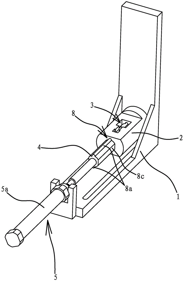
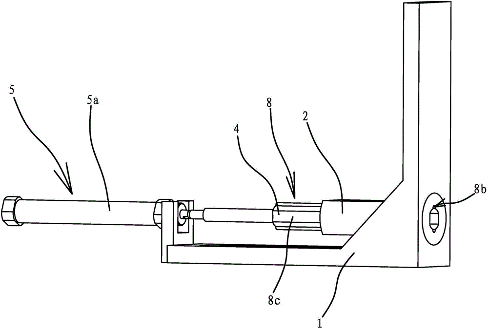
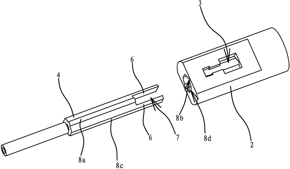
[0035] Such as Figures 1 to 4 , 7, the pushing mechanism in the feeding device includes a bracket 1 and a feeding cylinder 2 arranged on the bracket 1. One side of the feeding cylinder 2 is provided with a feed port-3, and the feed port-3 is connected to the feed tube 2. The cavities are connected, the feeding cylinder 2 is provided with a push rod 4, and the bracket 1 is also provided with a drive mechanism 5 that can drive the push rod 4 to reciprocate. The drive mechanism 5 is fixed on the bracket 1 for the cylinder body. Cylinder one 5a, the piston rod of cylinder one 5a is connected with push rod 4.
[0036] The inner end face of the pusher rod 4 has a protruding end face and a columnar pusher portion 6, the number of the pusher portion 6 is two, and there is a gap 7 between the two pusher portions 6, the cylinder one 5a can Drive the push rod 4 to move in translation so that the gap 7 can be opposite to the feeding port 3 of the feeding cylinder 2 . The pusher part 6 ...
Embodiment 2
[0045] The structure and principle of this embodiment are basically the same as that of Embodiment 1, the difference is that: Figure 5 and 6 As shown, the upper side of the feeding cylinder 2 is fixedly connected with a strip-shaped guide 11 , and the guide 11 is arranged perpendicular to the axis of the feeding cylinder 2 . The upper side of the guide 11 has a guide groove 11a, the guide groove 11a is arranged along the axial direction of the guide 11, and the bottom of the guide groove 11a is provided with a penetrating feed inlet 11b, and the feed inlet 11b is connected to the feed cylinder 2. There is a one-to-one correspondence between the structure and the position of the feeding port-3. The guide groove 11a is embedded with a blanking plate 9, and the feeding cylinder 2 is also positioned with a drive mechanism 2 10 that can drive the blanking plate 9 to reciprocate. The blanking plate 9 is provided with a feed port 9a, and a feed port 9a Vertically penetrating on th...
PUM
 Abstract
Description
Claims
Application Information