Occupant protection system

a technology for occupant protection and seat, which is applied in the direction of pedestrian/occupant safety arrangement, vehicle components, vehicle arrangement, etc., can solve the problems of complicated work of mounting the occupant protection system to the seat, and achieve the effect of convenient mounting to the sea

Inactive Publication Date: 2009-03-03
JOYSON SAFETY SYST JAPAN KK
View PDF16 Cites 12 Cited by
  • Summary
  • Abstract
  • Description
  • Claims
  • Application Information

AI Technical Summary

Benefits of technology

[0005]It is an object of the present invention to provide an occupant protection system that can easily be mounted to a seat.
[0006]An occupant protection system according to an embodiment of the present invention includes a seat pan arranged below a seat cushion, an inflatable airbag arranged above the seat pan for pushing the front section of the seat cushion from below, and a gas generator for inflating the airbag in an emergency. Both the airbag and the gas generator are mounted to the seat pan. Accordingly, when mounting the occupant protection system to a seat, it is sufficient to mount the seat pan, to which the airbag and the gas generator are fixed in advance, below the seat cushion. Thus, the occupant protection system can be easily mounted to the seat.
[0007]The airbag can extend along the width direction of the seat pan, opposite ends of the airbag being connected to the seat pan. Extending the airbag along the width direction of the seat pan and connecting the opposite ends to the seat pan allows the airbag to be inflated uniformly between its ends and allows the front section of the seat cushion to be pushed uniformly from below along the width direction.
[0008]The gas generator can be arranged along the upper surface or the lower surface of the seat pan. Arranging the gas generator along the upper surface of the seat pan can facilitate the connection between the gas generator and the airbag. Arranging the gas generator along the lower surface of the seat pan can increase the flexibility of the arrangement of the gas generator.

Problems solved by technology

Thus, the work to mount the occupant protection system to the seat is complicated.

Method used


Image

  • Occupant protection system
  • Occupant protection system
  • Occupant protection system

Examples


Embodiment Construction

[0016]Embodiments of the present invention will be described below with reference to the drawings.

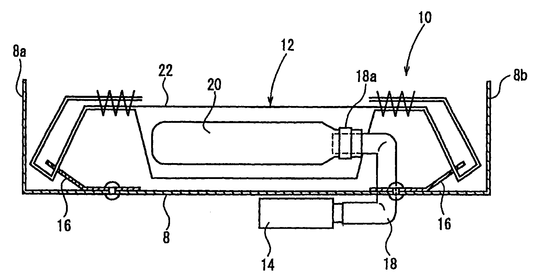
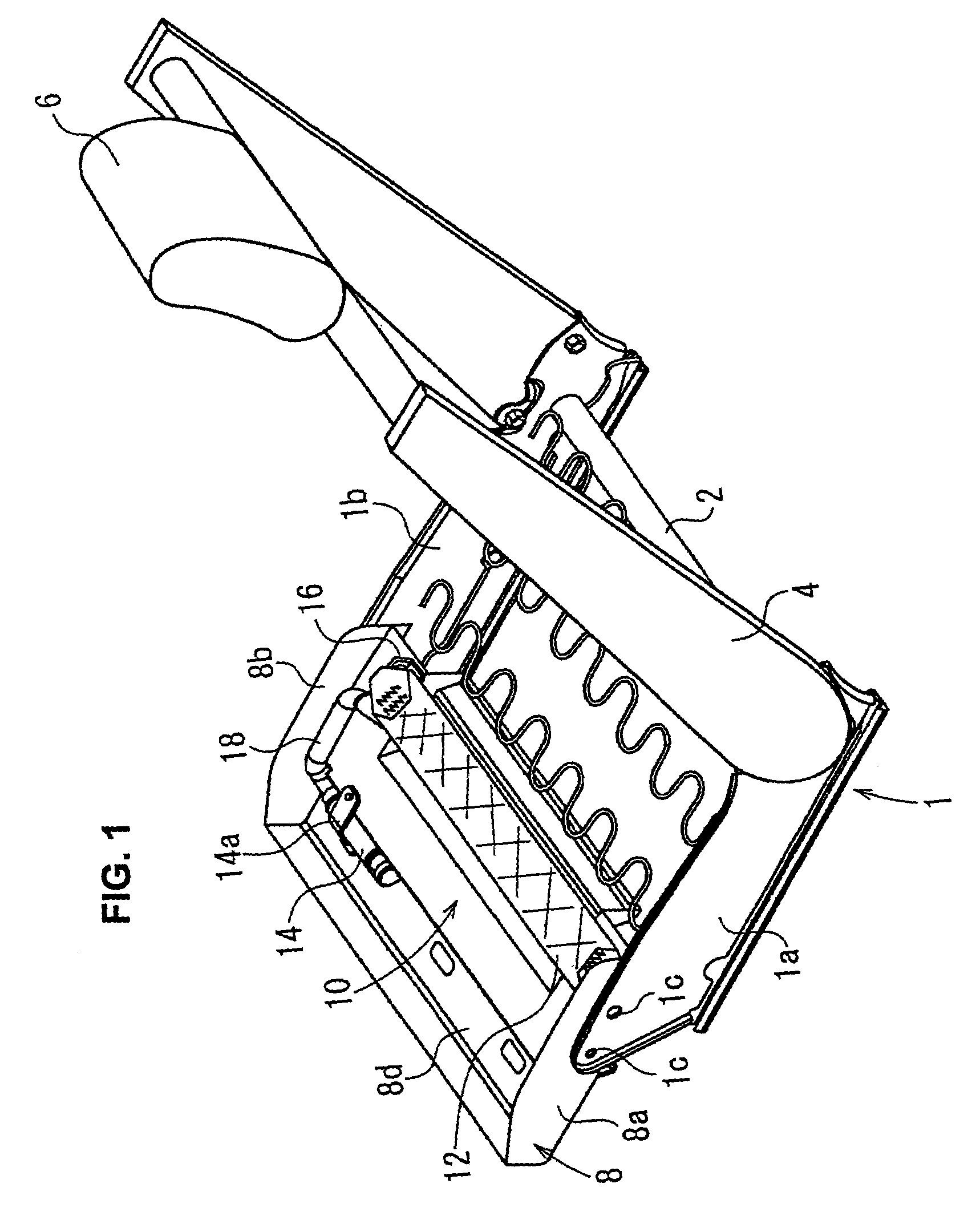
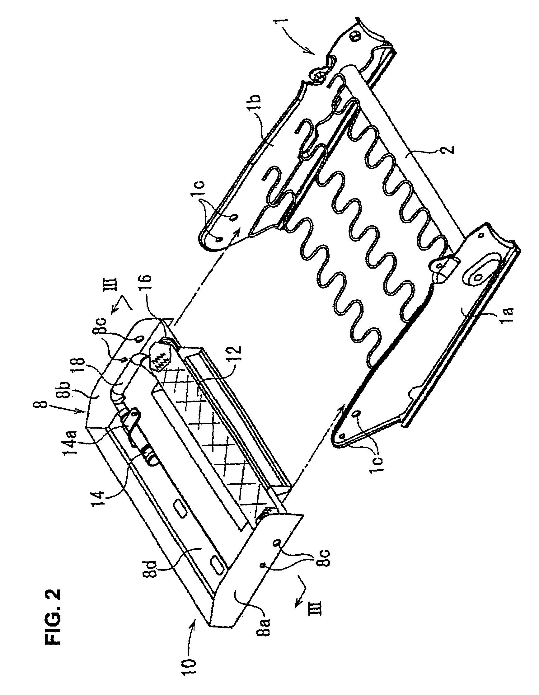
[0017]FIG. 1 is a perspective view of the frame of a seat provided with an occupant protection system according to an embodiment of the present invention; FIG. 2 is an exploded perspective view of the occupant protection system and the frame; and FIG. 3 is a sectional view of the occupant protection system in FIG. 2, taken along line III-III.

[0018]The frame of the car seat includes a base frame 1 and a back frame 4 rotatably connected to the base frame 1 through a support shaft 2 and a reclining device (not shown). A headrest 6 is mounted on the top of the back frame 4.

[0019]The base frame 1 includes left and right side frames 1a and 1b. A seat pan 8 is placed between the front parts of the side frames 1a and 1b. The seat pan has uprising side walls 8a and 8b that can be placed along the inner surfaces of the side frames 1a and 1b, respectively. Where the side frames 1a and 1b and the s...


PUM


Abstract

An occupant protection system, which can easily be mounted to a seat, includes a seat pan placed between the front parts of the side frames of a seat, an airbag arranged above the seat pan, and a gas generator for inflating the airbag. The airbag extends along the width direction of the seat pan, opposite ends of the airbag being connected to the seat pan through anchors. The gas generator is arranged on the upper surface of the seat pan and is fixed to the seat pan with a bracket. The gas generator is connected to the airbag via a pipe.

Description

BACKGROUND[0001]The present invention relates to an occupant protection system for protecting an occupant of a vehicle, such as a car, in the event of a crash. More specifically, the present invention relates to an occupant protection system for restraining the lumbar part of the occupant during a front crash to prevent the body of the occupant from moving forward and downward.[0002]Japanese Unexamined Patent Application Publication No. 2001-247010 discloses an occupant protection system for protecting an occupant in the event of a car crash. When a crash occurs, the system heightens or hardens the front section of a seat cushion in order to prevent a so-called submarine phenomenon, in which the occupant passes under the lap belt during a front crash.[0003]FIG. 34 of Japanese Unexamined Patent Application Publication No. 2001-247010 shows an airbag that is placed between a left side frame and a right side frame of a seat and a gas generator that is disposed on the side of one of the...

Claims


Application Information

Patent Timeline
Patent Type & Authority Patents(United States)
IPC IPC(8): B60R21/207B60N2/42B60N2/427B60R21/02B60R21/16B60R21/20B60R21/231B60R21/233B60R21/26B60R21/261
CPCB60N2/42763B60N2/4279B60R21/207B60R21/23184B60R2021/23332B60R2021/2612
Inventor SAKAI, KATSUYUKINOJIRI, KEIICHIRO
Owner JOYSON SAFETY SYST JAPAN KK
Why Eureka
Try Eureka