Mass Spectrometer

a mass spectrometer and time-offlight technology, applied in the field of time-offlight mass spectrometers, can solve the problems of increasing the flight distance along a straight line, increasing the size of the apparatus, and system design is not always easy, so as to achieve the effect of widening the mass range, enhancing the mass accuracy and mass resolving power, and forming a long flight distance in a small spa

Inactive Publication Date: 2011-07-28
SHIMADZU CORP
View PDF14 Cites 22 Cited by
  • Summary
  • Abstract
  • Description
  • Claims
  • Application Information

AI Technical Summary

Benefits of technology

[0034]With the mass spectrometers according to the first through third aspects of the present invention, a loop orbit that satisfies the condition for the temporal focusing of the ions while ensuring a long flight distance can be formed in a small space. Particularly, in these mass spectrometers, a large number of basic ion optical systems can be sequentially connected so as to realize a compact system while extremely elongating the one-turn length of the loop orbit. This enhances the mass accuracy and mass resolving power. The increase in the one-turn length widens the mass range within which no catching or overtaking of the ions occurs during their flight. The downsizing of the entire system, and particularly the reduction in its installation area, is easy to achieve. The entire ion optical system can be designed with a higher degree of freedom and by relatively easy design work, in which only the condition for the temporal focusing of the ions on a plane needs to be considered for the design of the size, shape, arrangement and other elements of the electrodes used for forming the sector-shaped electric fields.

Problems solved by technology

However, increasing the flight distance along a straight line is impractical because it inevitably leads to an increase in the size of the apparatus.
Such a system is not always easy to design.
However, when ions having different masses are mixed, an ion having a smaller mass and flying faster catches and overtakes another ion having a larger mass and flying more slowly, which makes it difficult to distinguish these ions.
However, this does not absolutely guarantee that the focusing condition of the ions for the entire helical orbit will also be satisfied.
Therefore, for example, it is possible that the sensitivity is deteriorated due to the dispersion of a portion of the ions or that the achieved mass accuracy or mass resolving power is lower than expected.
Particularly, these problems are likely to occur when the number of turns is increased to elongate the flight distance.Patent Document 1: JP-A H11-297267Non-Patent Document 1: H. Matsuda, “Improvement of a TOF Mass Spectrometer with Helical Ion Trajectory,”Journal of the Mass Spectrometry Society of Japan, 49, p.

Method used


Image

  • Mass Spectrometer
  • Mass Spectrometer
  • Mass Spectrometer

Examples


Embodiment Construction

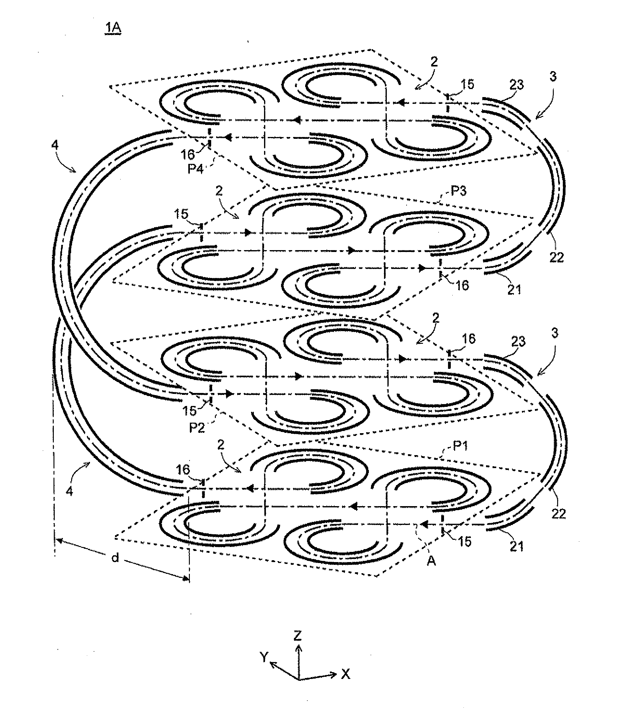
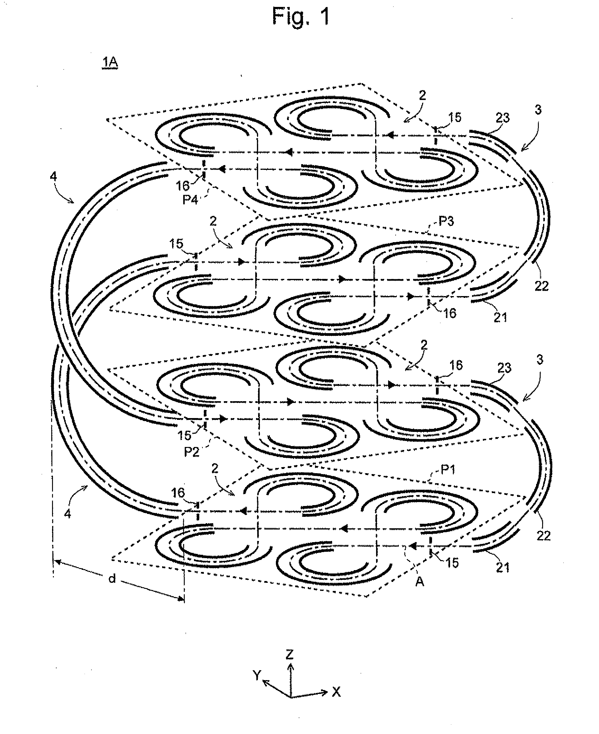
[0053]In advance of the explanation of embodiments of the mass spectrometer according to the present invention, examples of the aforementioned ion optical system proposed in the Internal Patent Application No. PCT / JP2007 / 000548 are hereinafter briefly described by means of FIGS. 6-9. FIGS. 6 and 7 are schematic perspective views of ion optical systems proposed in PCT / JP2007 / 000548. FIGS. 8 and 9 are plan views respectively showing conventional linear-type and loop-type ion optical systems.

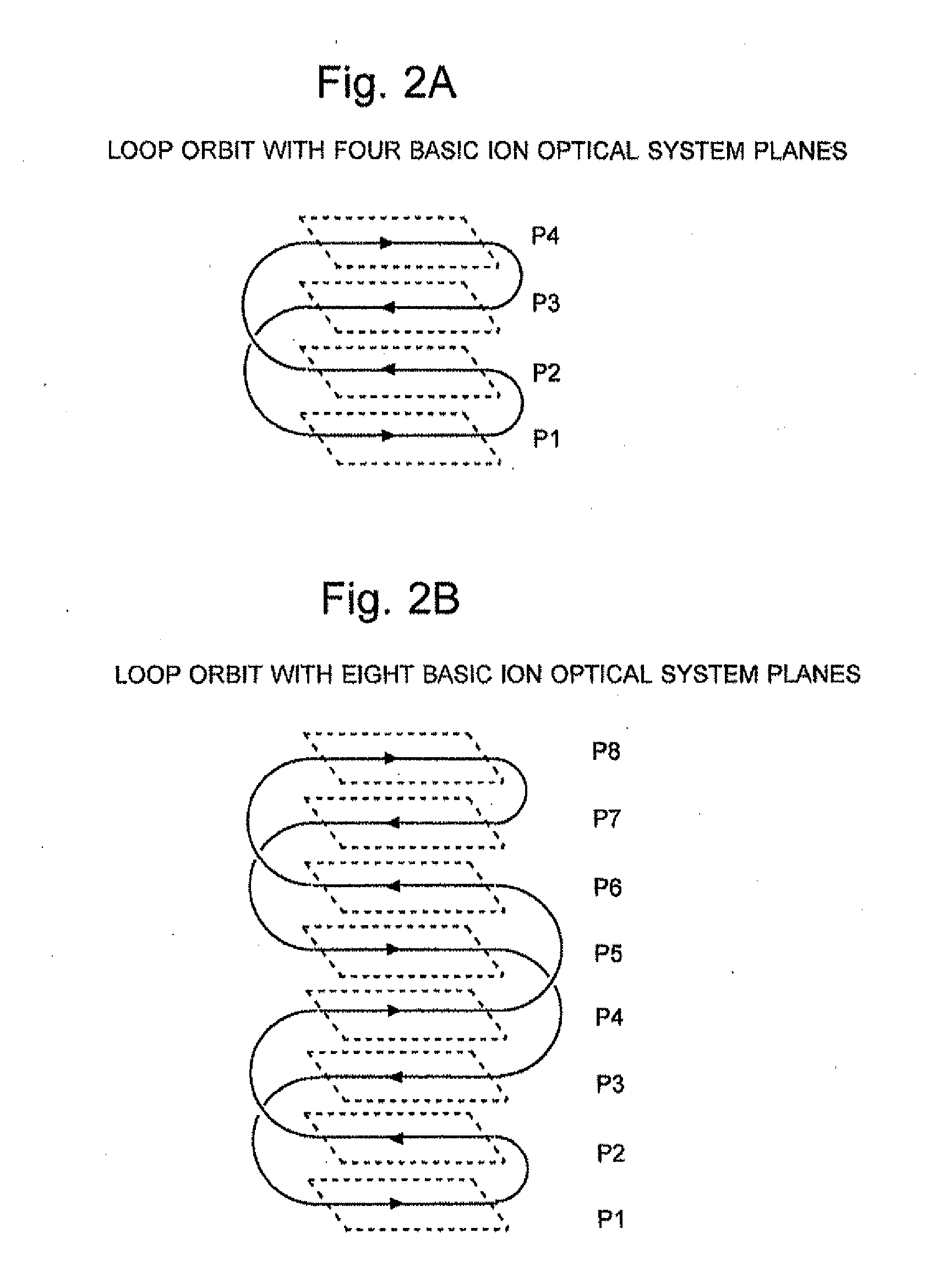
[0054]The ion optical system 1E shown in FIG. 6 includes an array of three basic ion optical system planes P1, P2 and P3 spaced in the Z-direction. Each of these planes extends parallel to the X-Y plane, with a first basic ion optical system 2 formed thereon. The orbits on the basic ion optical system planes P1 and P2 as well as P2 and P3 neighboring in the Z-direction are connected by second basic ion optical systems 3.

[0055]The first basic ion optical system 2 is one example of the ion optical sy...


PUM


Abstract

A basic ion optical system having a guaranteed capability for the temporal focusing of ions, including sector-shaped electrodes, an injection slit and an ejection slit, is arranged on the same plane. Four or more sets of the basic ion optical systems are arrayed at predetermined intervals in a direction substantially orthogonal to the aforementioned plane. The injection slit on a topmost basic ion optical system plane and the ejection slit on a basic ion optical system plane located immediate below, as well as the injection slit on a bottommost basic ion optical system plane and the ejection slit on a basic ion optical system plane located immediate above, are respectively connected by another type of basic ion optical system having a guaranteed capability for the temporal focusing of ions. The other injection slits and ejection slits are respectively connected by another type of basic ion optical system having a guaranteed capability for the temporal focusing of ions. Thus, a loop orbit having a three-dimensionally deformed figure “8”-shape is formed, whereby the flight distance is elongated while ensuring the temporal focusing of the ions for the entire system, simultaneously with utilizing the three-dimensional space to compactify the ion optical system.

Description

TECHNICAL FIELD[0001]The present invention relates to a time-of-flight mass spectrometer, and more specifically to an ion optical system for forming a flight space in which ions are made to fly within a time-of-flight mass spectrometer.BACKGROUND ART[0002]Typically, in a time-of-flight mass spectrometer (TOF-MS), the time required for an ion to fly a certain distance is measured so as to calculate the mass of the ion from the time of flight, based on the fact that an ion accelerated by a certain amount of energy has a flight speed corresponding to its mass. Accordingly, increasing the flight distance is particularly effective for improving the mass resolving power. However, increasing the flight distance along a straight line is impractical because it inevitably leads to an increase in the size of the apparatus. To overcome this limitation, a variety of optical systems with different configurations for forming a flight space have been conventionally devised.[0003]One example of such...

Claims


Application Information

Patent Timeline
Patent Type & Authority Applications(United States)
IPC IPC(8): H01J49/40
CPCH01J49/408
Inventor YAMAGUCHI, SHINICHI
Owner SHIMADZU CORP
Why Eureka
Try Eureka