Image blur correction device, imaging lens unit, and camera unit

a technology of image blur correction and imaging lens, which is applied in the direction of television systems, printing, instruments, etc., can solve the problems of difficult drive control for positioning les within a plane vertical to the optical axis, increase in the size of the first drive device, and increase in the size of the drive device, so as to reduce and improve the accuracy of correcting an image blur caused. , the effect of reducing the size and thickness of the devi

Inactive Publication Date: 2011-07-28
COPAL CO LTD
View PDF10 Cites 17 Cited by
  • Summary
  • Abstract
  • Description
  • Claims
  • Application Information

AI Technical Summary

Benefits of technology

[0043]According to the image blur correction device having the above-described configuration, it is possible to obtain the image blur correction device that can be applied to the camera unit mounted in, e.g., a mobile phone while achieving, e.g., simplification of the structure or a reduction in size and thickness of ...

Problems solved by technology

However, this device adopts a double configuration that the first movable member and the second movable member are aligned in an optical axis direction, thus leading to an increase in size of the device in the optical axis direction.
Further, although the second drive device drives the second movable member alone, the first drive device must drive not only the first movable member but also the second movable member and the second guide shaft at the same time, larger drive force must be generated as compared with a situation where the first movable member alone is driven, thereby resulting in an increase in size of the first drive device.
Furthermore, since a drive load of the first drive device is different from a drive load of the second drive device, drive control for positioning the les within a plane vertical to the optical axis is not easy.
Additionally, although the base is coupled with the...

Method used


Image

  • Image blur correction device, imaging lens unit, and camera unit
  • Image blur correction device, imaging lens unit, and camera unit
  • Image blur correction device, imaging lens unit, and camera unit

Examples


Embodiment Construction

[0156]The best mode for carrying out the present invention will now be described with reference to the accompanying drawings hereinafter.

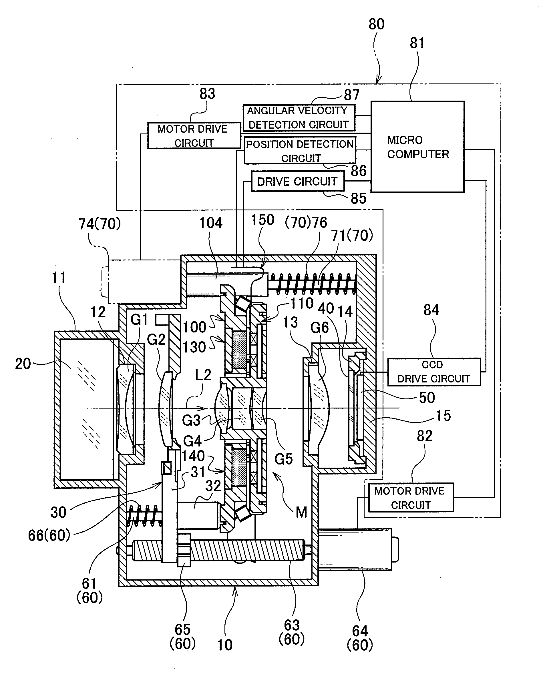
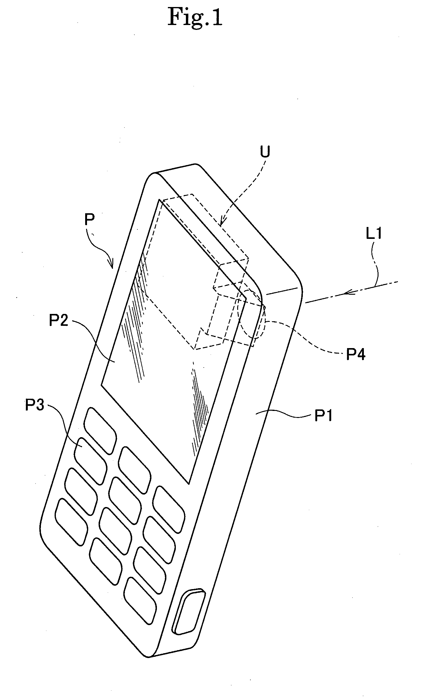
[0157]As shown in FIG. 1, a camera unit U having an image blur correction device (image stabilization device) incorporated therein is mounted in a flat and small personal digital assistance P. The personal digital assistance P includes a housing P1 having a substantially rectangular and flat outline form, a display unit P2 such as a liquid crystal panel that is arranged on a surface of the housing P1 and displays various kinds of information, operation buttons P3, an imaging window P4 formed on a surface of on the opposite side of the display unit P2, and others. Further, as shown in FIG. 1, the camera unit U is accommodated in the housing P1 so as to extend in a direction vertical to an optical axis L1 of subject light that enters from the imaging window P4.

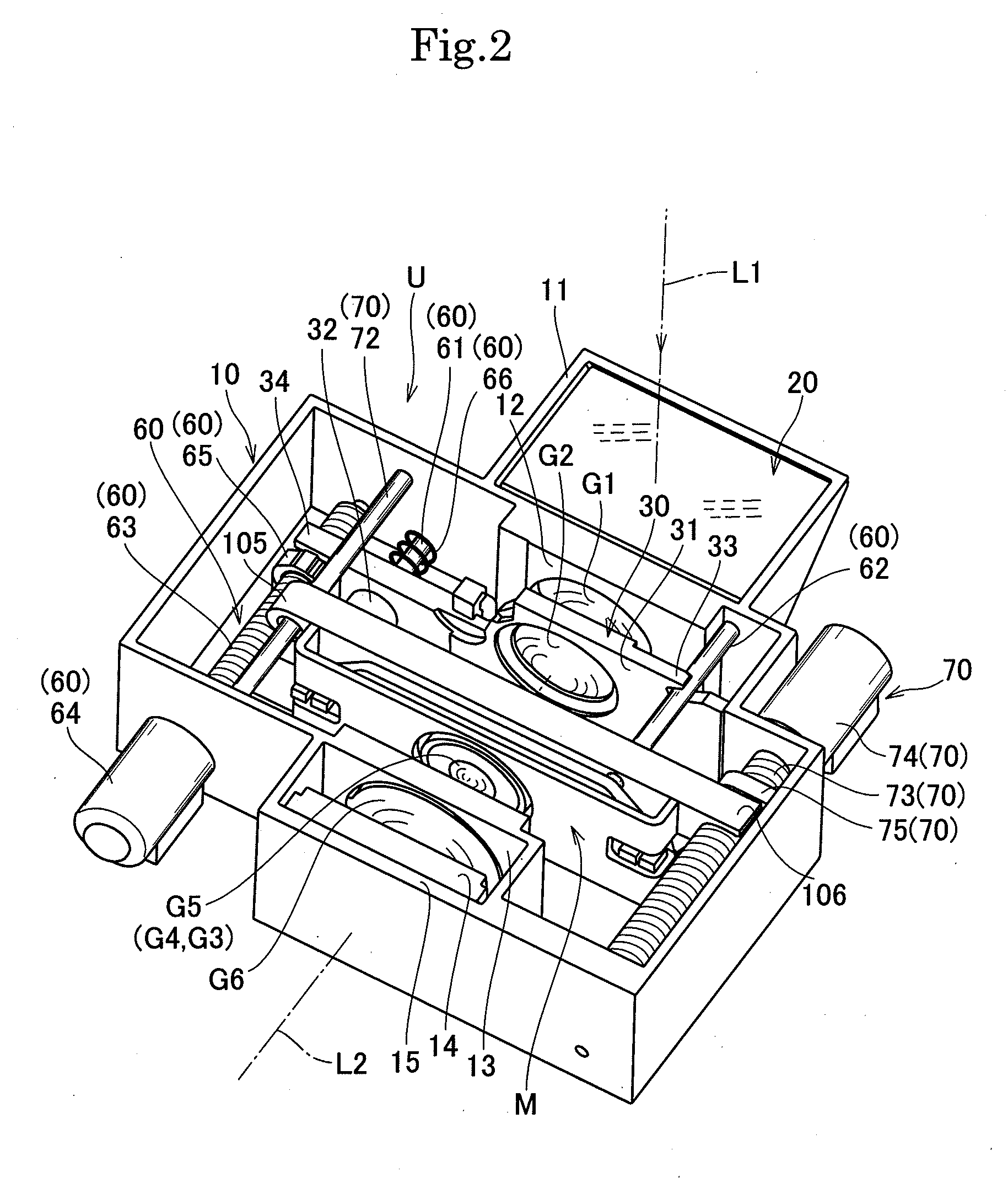
[0158]As shown in FIG. 2 and FIG. 3, the camera unit U includes: a unit case 10; a prism 20...


PUM


Abstract

An image blur correction device according to the present invention includes: a tabular base (100) having an opening portion (101) opened in an optical axis direction; a tabular movable holding member (110) configured to hold a lens and supported to be movable within a plane vertical to an optical axis of the lens; a first drive mechanism (130) including a first magnet and a first coil so as to drive the movable holding member in a first direction vertical to the optical axis; a second drive mechanism (140) including a second magnet and a second coil so as to drive the movable holding member in a second direction vertical to the optical axis; and a detecting means (170, 180) for detecting a position of the movable holding member, wherein the movable holding member is movably supported to be adjacent to the base, and the first drive mechanism and the second drive mechanism are arranged at positions that are line-symmetric with respect to a first straight line (S1) perpendicular to the optical axis of the lens. The configuration allows the device to be reduced in size and thickness and can highly accurately correct a shift of the optical axis of the lens due to hand shaking and others.

Description

TECHNICAL FIELD[0001]The present invention relates to an image blur correction device (image stabilization device) mounted in, e.g., a lens body tube or a shutter unit in a digital camera, and to an imaging lens unit and a camera unit including this image blur correction device, and more particularly to a small and thin image blur correction device (image stabilization device) applied to a camera unit mounted in a personal digital assistance such as a mobile phone, and to an imaging lens unit and a camera unit.BACKGROUND ART[0002]As a conventional image blur correction device (image stabilization device), there is known an image blur correction device including: a substantially rectangular base having an opening portion at the center; a first guide shaft provided on a front surface of the base; a first movable member supported to be reciprocable along the first guide shaft; a second guide shaft directed to a 90-degree direction with respect to the first guide shaft and provided on a...

Claims


Application Information

Patent Timeline
IPC IPC(8): G02B27/64G03B17/00
CPCG03B5/00G03B17/02G03B17/04H04N5/23258H04N5/2254H04N5/23248H04M1/0264H04N23/55H04N23/68H04N23/6812
Inventor WATANABE, HIROYUKI
Owner COPAL CO LTD
Why Eureka
Try Eureka