
Lancing device

a technology of lancing device and lancing device, which is applied in the field of lancing device and improving lancing device, can solve the problems of cumbersome and inefficient devices, cumbersome and not easily manipulated devices, and particularly difficult manipulations

Active Publication Date: 2011-07-28
ASCENSIA DIABETES CARE HLDG AG
View PDF16 Cites 44 Cited by
  • Summary
  • Abstract
  • Description
  • Claims
  • Application Information

AI Technical Summary

Benefits of technology

In such a lancing device, the actuator may further comprise a raised member to assist with movement thereof.

Problems solved by technology

Most patients find it undesirable to pierce their own skin with a piercing device, so automatic lancing devices have become the norm.
Heretofore, such devices have been cumbersome and not efficient.
Predominantly, such devices have been pen-shaped, which can be cumbersome and not easily manipulated.
Difficult manipulation is particularly problematic when the diabetic is a child, an elderly person, someone with a handicap, or one with limited dexterity.

Method used


Image

  • Lancing device
  • Lancing device
  • Lancing device

Examples


first embodiment

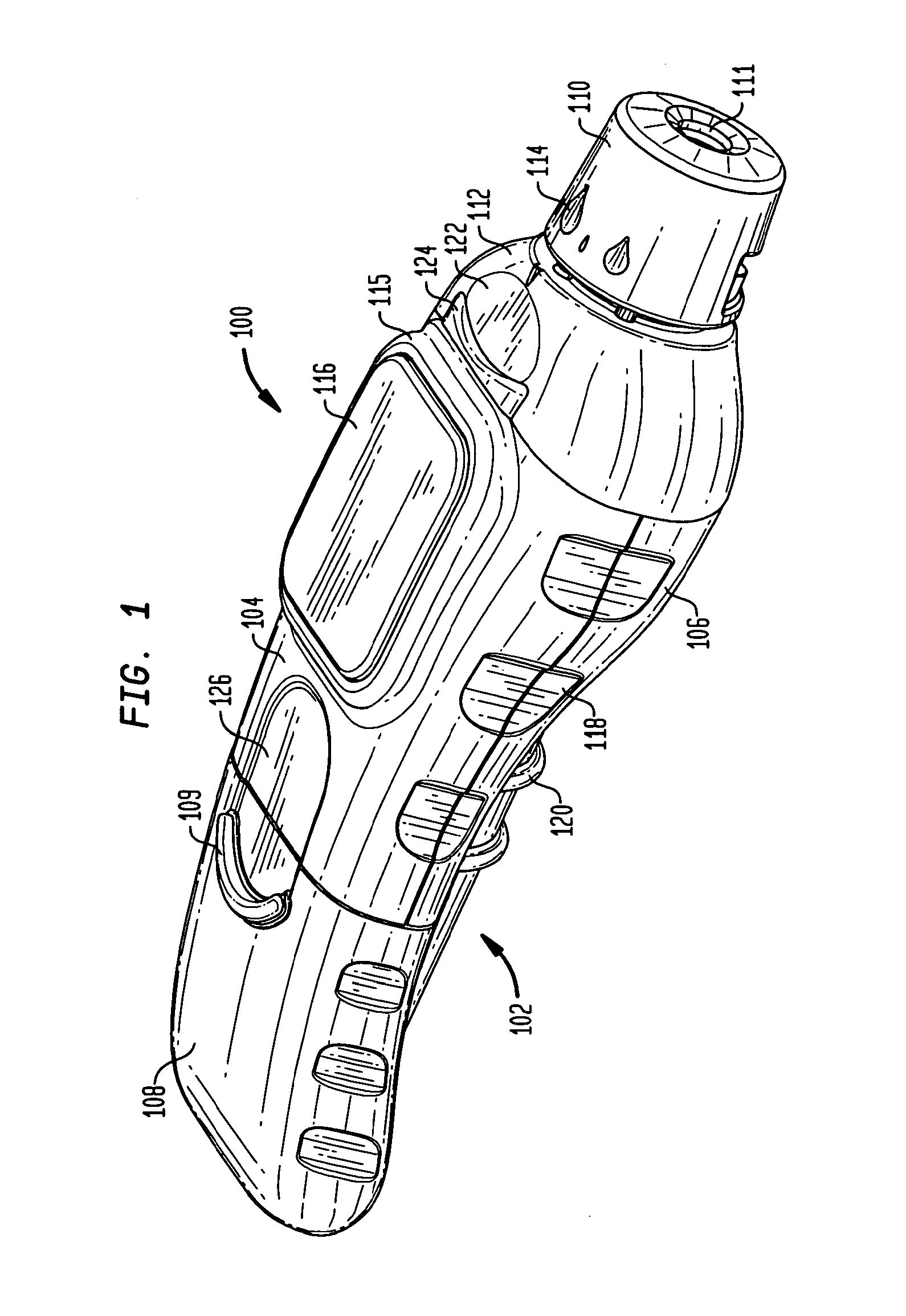
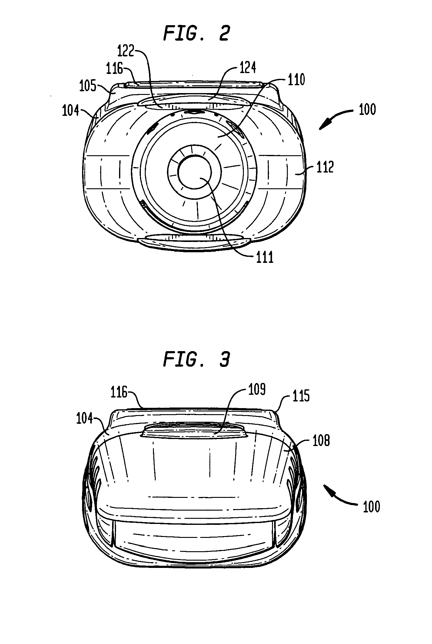
Referring to FIG. 1, a perspective view of a lancing device in accordance with the present invention, it will be appreciated that the lancing device 100 may include a main body 102 configured from an upper portion 104, a lower portion 106 mated to the upper portion, and an actuator 108. The lancet device 100 may further include an endcap 110 mounted to the upper and lower portions 104, 106 by endcap shoulders 112.

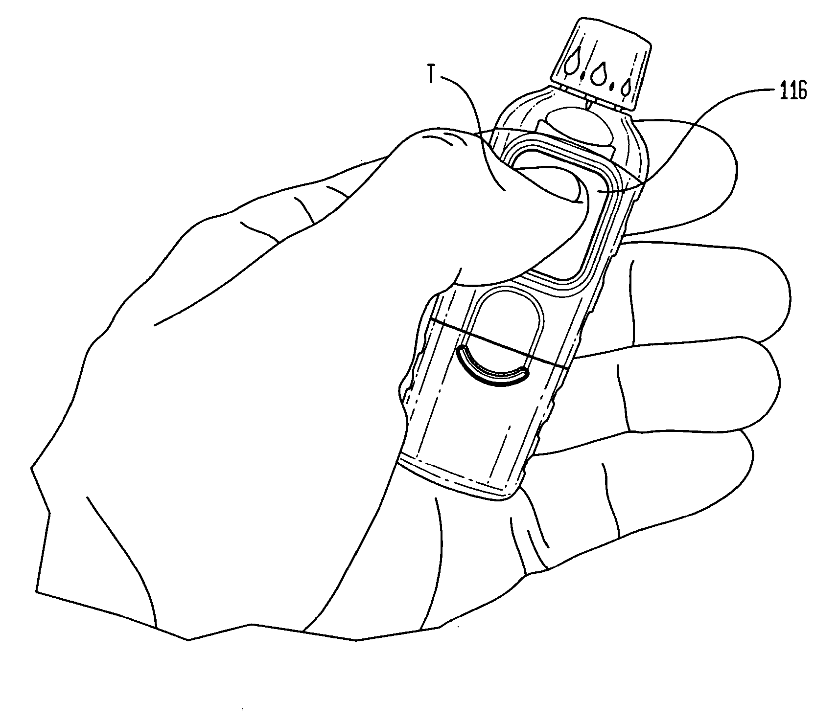
The combination of upper portion 104 and actuator 108 are preferably configured to be of roughly the same length as the lower portion 106. As will be appreciated when discussing use of the device, this enables the lower portion 106 to be retained in stationary relation with the palm of a user's hand while the actuator 108 is moved away from the endcap 110 and then toward the endcap.

In the particular embodiment shown in FIG. 1, the endcap 110 is an adjustable endcap, whereby rotation of the endcap to the various positions indicated by the sized blood drops 114a-c (see FIG. 6...

second embodiment

Moving briefly to the lancing device, shown in FIGS. 8-14, it will be appreciated that the endcap 112′ may be fixed, such that excursion of the lancet from within the device is similarly fixed. In this regard, the level of penetration into a patient is fixed. Moreover, the endcap is preferably substantially clear or translucent such that a user can view the lancet piercing the skin and may further manipulate the main body after piercing to enlarge the penetration. When sufficient blood is witnessed through the clear window, the user may then remove the lancet from the skin. In other embodiments the endcap may be provided as an opaque endcap.

The components previously listed, including the main body components and the two endcaps 112, 112′, are preferably constructed from plastic. It will be appreciated that any of the components, particularly the endcaps 112, 112′, may be configured from an antimicrobial plastic. Moreover, it is preferred that the upper and lower housings 104, 106 be...


PUM


Abstract

A lancing device formed from a main body and a cap. The main body is configured from a lower housing, an upper housing extending over a portion of the lower housing, and an actuator operatively engaged to the upper and lower housings with the actuator extending along the portion of the lower housing not covered by the upper housing. The upper housing further includes an actuator button, wherein a lancet may be placed within the body such that movement of the actuator from a first position to a second position away from said endcap cocks the lancet for firing, which is achieved by depressing the actuator button. Conveniently, the lancing device is configured for tactile recognition in the palm of a human hand and may preferably be operated one handed and without visual observation.

Description

TECHNICAL FIELDThis invention relates generally to devices utilized in the evaluation of glucose levels in patients with diabetes. More specifically, the present invention is directed toward improved lancing devices of the type utilized to pierce a patient's skin to produce a blood sample for glucose measurement. The lancing devices contemplated here are more ergonomic than prior devices (such as by being curved for orientation in the palm of a hand), which are predominantly pen-shaped, and therefore allow a previously unforeseen ease of use. This use extends to permitting one handed use through tactile manipulation, thus freeing the user's other hand and visual orientation for alternate endeavors.BACKGROUND OF THE INVENTIONIt is well known that individuals with diabetes may monitor their blood glucose levels several times per day. This is typically accomplished by piercing the skin with a lancet, most commonly in the area of a finger or forearm, and then placing a blood droplet fro...

Claims


Application Information

Patent Timeline
Patent Type & Authority Applications(United States)
IPC IPC(8): A61B17/34
CPCA61B5/1411A61B5/150022A61B5/150068A61B5/150183A61B5/150259A61B5/150412A61B5/15194A61B5/150816A61B5/150824A61B5/150832A61B5/15113A61B5/15117A61B5/1519A61B5/150435
Inventor BROWN, DANIELMATHELIER, MARTIN ANTOINELORZA, MARIA ISABELMCCLOUD, WILLIAMPURCELL, GLENNWALKER, TOMCHOI, SEHEGEUNWALSH, PHILIP
Owner ASCENSIA DIABETES CARE HLDG AG
Learn More