Pipe handling apparatus for presenting sections of pipe to a derrick work floor having a high-speed carriage assembly

a technology of pipe handling apparatus and derrick work floor, which is applied in the direction of drilling pipes, loading/unloading, drilling casings, etc., can solve the problems of limited response time, significant time-consuming and laborious pipe handling operations, and low average speed of the carriage, so as to reduce friction, reduce friction, and reduce the effect of pressur

Active Publication Date: 2006-04-04
FORUM US
View PDF10 Cites 42 Cited by
  • Summary
  • Abstract
  • Description
  • Claims
  • Application Information

AI Technical Summary

Benefits of technology

[0015]In a further embodiment of the invention there is further provided an idler carriage member, longitudinally separated along the boom from said carriage, and slidably coupled to the boom and moveable longitudinally along the boom for assisting movement of pipe longitudinally along the trough when pipe is engaged with the drive carriage.
[0016]Each carriage member further, in a preferred embodiment, comprises means for reducing friction and facilitating movement of the base member along the boom, which in a preferred embodiment comprises a plurality of rollers situate between the base member and the trough. Examples of alternate means for reducing friction include: liquid lubricants such as oil, gases such as air or an inert gas under pressure, and opposing electro-magnetic fields.
[0017]In a further aspect, the carriage apparatus of the present invention, contemplates a wide-track, double-edge surround guide pair, with a low-profile base that is slideably coupled to a reinforced boom that also operates as a track, and a single or dual drive-line for bi-directional motion under power. Advantageously, by moving in the pipe trough the apparatus of the present invention achieves a full range of longitudinal motion while eliminating the cavity of older pipe car designs and reducing the pressure applied to the surface on which the apparatus glides. Further, a significant advantage results over the slower moving hydraulic pusher assemblies in that the average speed of the carriage of the present invention is higher permitting pipe handling operations to be accelerated.
[0018]According to a preferred dual drive-line implementation, the apparatus of the present invention is made more reliable and further stabilized since either drive-line may propel the carriage. Each drive-line adds to the mass of the entire assembly, creating an inertial or runaway dampening effect in the event that power is lost to either the drive motor or to the braking assembly. Advantageously, overhanging channel members are provided which prevent disengagement of the carriage with the trough thereby overcoming the problem of the limited coupling achieved in designs having only four discrete points on tracks, by substantially fully encompassing both sides of a reinforced boom along the entire length of the carriage being coupled thereto, resulting in more extensive coupling to the trough. Further, the positioning of the drive-lines on both sides of the carriage results in additional force securing the carriage to the boom at the same time as resisting the twisting action to which a single center-point attachment is more prone.

Problems solved by technology

Disadvantageously, '519 and similar “ram based” designs that push a carriage member up the center of a trough require heavy, bulky hydraulic cylinders that are often restricted along the trough they can move a carriage, and further have limited response times such that the average speed of the carriage is low, causing pipe handling operations to take significant time.
Disadvantageously, this wheeled pipe car design and other similar pipe car designs that are pulled by a single cable along a center line, although capable of running substantially the full length of the boom, are unstable and the wheels and axles tend to wear prematurely with the wheels binding in their guide tracks.
A further disadvantage of the discrete wheel & track based design is that the coupling of the pipe car to the pipe handling system takes place at only four discrete points on the tracks, at any given moment.
Very significantly the stability of the 221 design is problematic when the track in which the wheeled pipe car rides must move between the ground and work floor levels such that a reinforced track and a braking assembly become necessary.
No pipe car design incorporating such features and which provides a relatively inexpensive addition to a raiseable pipe-handling apparatus is known.
Designs based on pipe cars having discrete wheels situated in tracks provide a limited coupling of the pipe carrying device (“car”) to a relatively fragile set of members, resulting in a design that is less reliable, less stable and less safe than might be achieved using similar components.
Moreover, none of the prior art reviewed teaches a device that is driven in both directions on both sides, failing to address the risk of runaway pipe cars.

Method used


Image

  • Pipe handling apparatus for presenting sections of pipe to a derrick work floor having a high-speed carriage assembly
  • Pipe handling apparatus for presenting sections of pipe to a derrick work floor having a high-speed carriage assembly
  • Pipe handling apparatus for presenting sections of pipe to a derrick work floor having a high-speed carriage assembly

Examples


Embodiment Construction

[0028]Reference is to be had to FIGS. 1–7 in which identical reference numbers identify similar components.

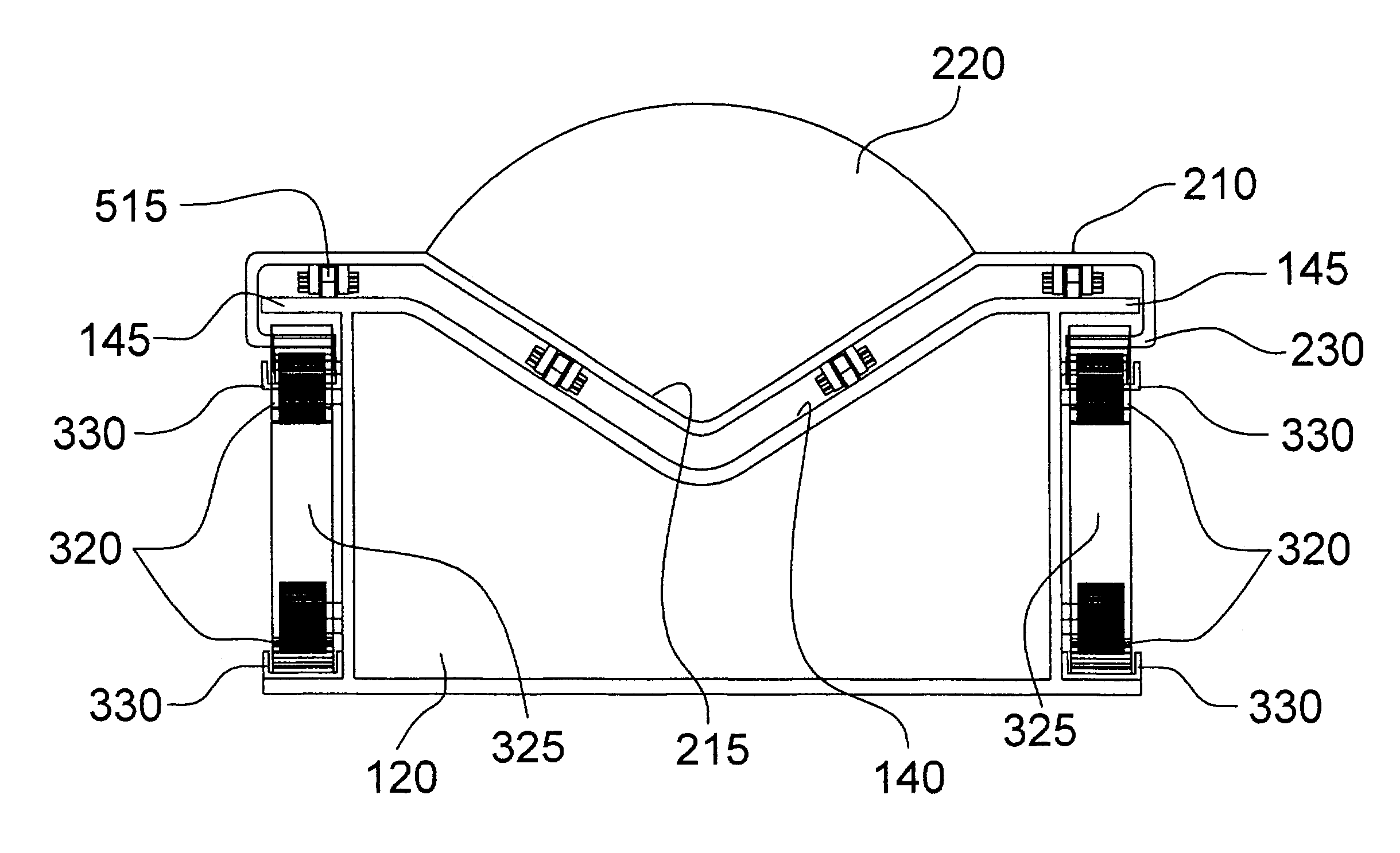
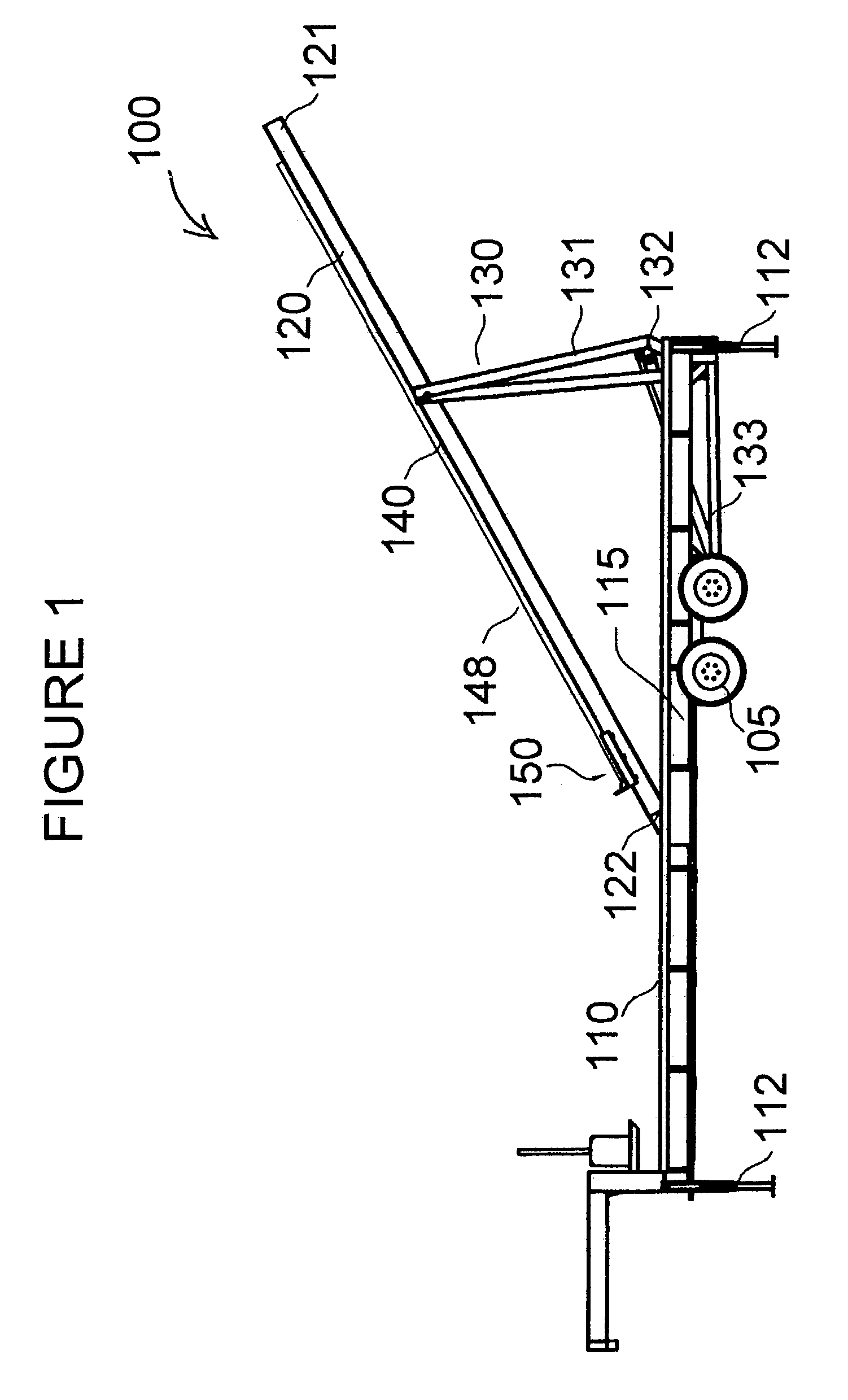
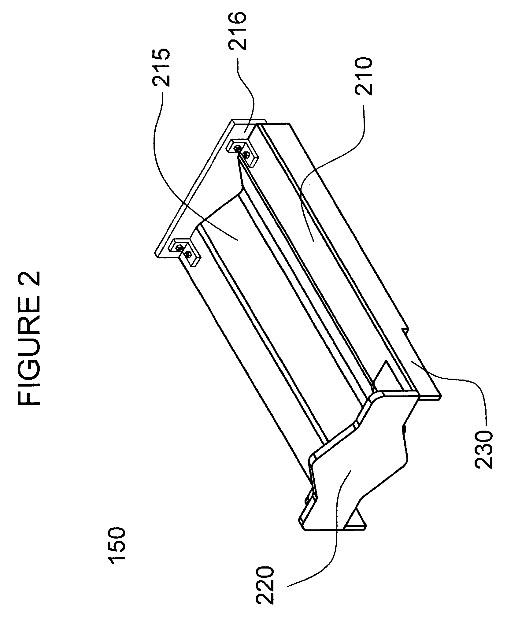
[0029]Referring to FIG. 1 there is illustrated a pipe handling system, denoted generally as 100 shown having base 110 mounted on undercarriage assembly 105 stabilized by legs 112 when in operation. Boom 120 is shown with proximal end 121 in a raised position moving toward a derrick work floor (not shown) with distal end 122 gliding along cavity 115 guided by track means (not shown), as actuating means 130 raises boom 120 out of cavity 115. Trough 140, having pipe 148 therein, extends longitudinally along boom 120 and may be formed therein or fastened thereon, but in either case trough 140 is adapted for receiving carriage assembly 150 adapted to be driven bi-directionally between the distal end 122 and the proximal end 121 of boom 120.

[0030]As shown in FIG. 1, carriage assembly 150 carries the distal end of pipe 148. The proximal end 121 of boom 120 is raised by any suitable ac...


PUM


Abstract

A pipe handling apparatus for raising and lowering pipe to and from a raised derrick work floor. The apparatus comprises a longitudinally-extending base, with a longitudinally-extending cavity therein. An elongate, longitudinally-extending boom member is provided, which is adapted for raising out of and nestable positioning in such cavity. The boom member has a longitudinally-extending trough therein on an upperside surface thereof, adapted to receive at least one section of pipe. At least one arm member is coupled to the boom member for raising a proximal end of such boom member. A carriage member, slidably coupled to the boom member, is moveable longitudinally along the boom in the trough. The carriage member is adapted to engage and slidably transport one end of the pipe along the trough. Motive means are provided to permit powered movement of the carriage member along the boom.

Description

FIELD OF THE INVENTION[0001]The invention relates generally to pipe handling systems, and in particular to an apparatus for providing drill pipe to, and receiving drill pipe from, the work floor of a derrick or rig.BACKGROUND OF THE INVENTION[0002]Drill strings of pipe for oil and gas wells are assembled or disassembled vertically on a derrick one joint at a time, and are stored horizontally on pipe racks situated on the ground adjacent the rig. The work floor of the rig is typically elevated substantially above the pipe rack such that transferring sections of pipe to and from the racks and the work floor is necessary, and further requires careful handling of the heavy pipe to protect the workers and the pipe.[0003]Conventional systems based on a boom having a pipe receiving trough in which pipe may be placed typically also include some way to assist with moving heavy sections of pipe along and out of such trough.[0004]A variety of pipe cars, skates, bumpers, conveyors, stops and ot...

Claims


Application Information

Patent Timeline
Patent Type & Authority Patents(United States)
IPC IPC(8): E21B19/00E21B19/15
CPCE21B19/15
Inventor MORELLI, VINCE E.HANDLEY, RICHARD ARNOLDSHIELS, DARRENFREEMAN, SEAN
Owner FORUM US
Why Eureka
Try Eureka