
Field serviceable and replaceable display assembly

a display and assembly technology, applied in the direction of electrical apparatus casings/cabinets/drawers, identification means, instruments, etc., can solve the problems of reducing theaffecting the service life of the display itself and its related electronic components, and affecting the service life of the display. , to achieve the effect of reducing the total number of electronic components required, removing the frame easily and quickly

Active Publication Date: 2018-11-01
MFG RESOURCES INT INC
View PDF3 Cites 42 Cited by
  • Summary
  • Abstract
  • Description
  • Claims
  • Application Information

AI Technical Summary

Benefits of technology

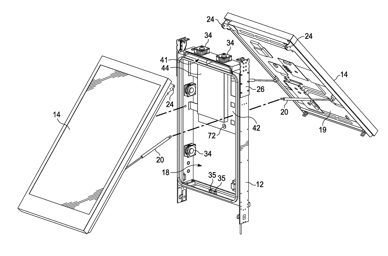
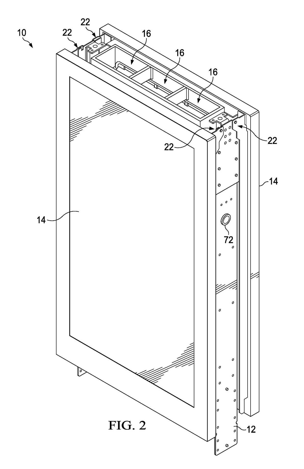
This patent is about a display assembly that can be opened for service without having to remove the display itself from its frame. The assembly has two aid devices that can be used to move the display between its open and closed positions, and secure it in those positions. The aid devices can also be used to open or close the display assembly. The display assembly is mechanically attached to the frame using a bracket and pin, making it easy to remove the digital displays, covers, and poster holders for servicing. The external power and communications connections are located on the frame or a plate between the components, so that the connections can be easily disconnected for servicing without disturbing the connection to the utility lines. The technical effects of this patent are that it provides a convenient way to service display assemblies without having to remove the display itself, and reduces the total number of electronic components required by sharing some of the components between the display assemblies.

Problems solved by technology

Despite efforts to protect the display from environmental conditions and other potential hazards, failures of the displays themselves and their related electronic components do occur.
Current assemblies for electronic displays make it difficult or impossible to service the display and the related electronic components.
Interaction with these utility lines generally subjects any servicing work to additional regulations and requires technicians having specialized knowledge.
Such efforts generally increase the costs, time, and effort involved with such servicing.
In this way, the external power and communications connections may often remain undisturbed.

Method used


Image

  • Field serviceable and replaceable display assembly
  • Field serviceable and replaceable display assembly
  • Field serviceable and replaceable display assembly

Examples


Embodiment Construction

)

[0031]Various embodiments of the present invention will now be described in detail with reference to the accompanying drawings. In the following description, specific details such as detailed configuration and components are merely provided to assist the overall understanding of these embodiments of the present invention. Therefore, it should be apparent to those skilled in the art that various changes and modifications of the embodiments described herein can be made without departing from the scope and spirit of the present invention. In addition, descriptions of well-known functions and constructions are omitted for clarity and conciseness.

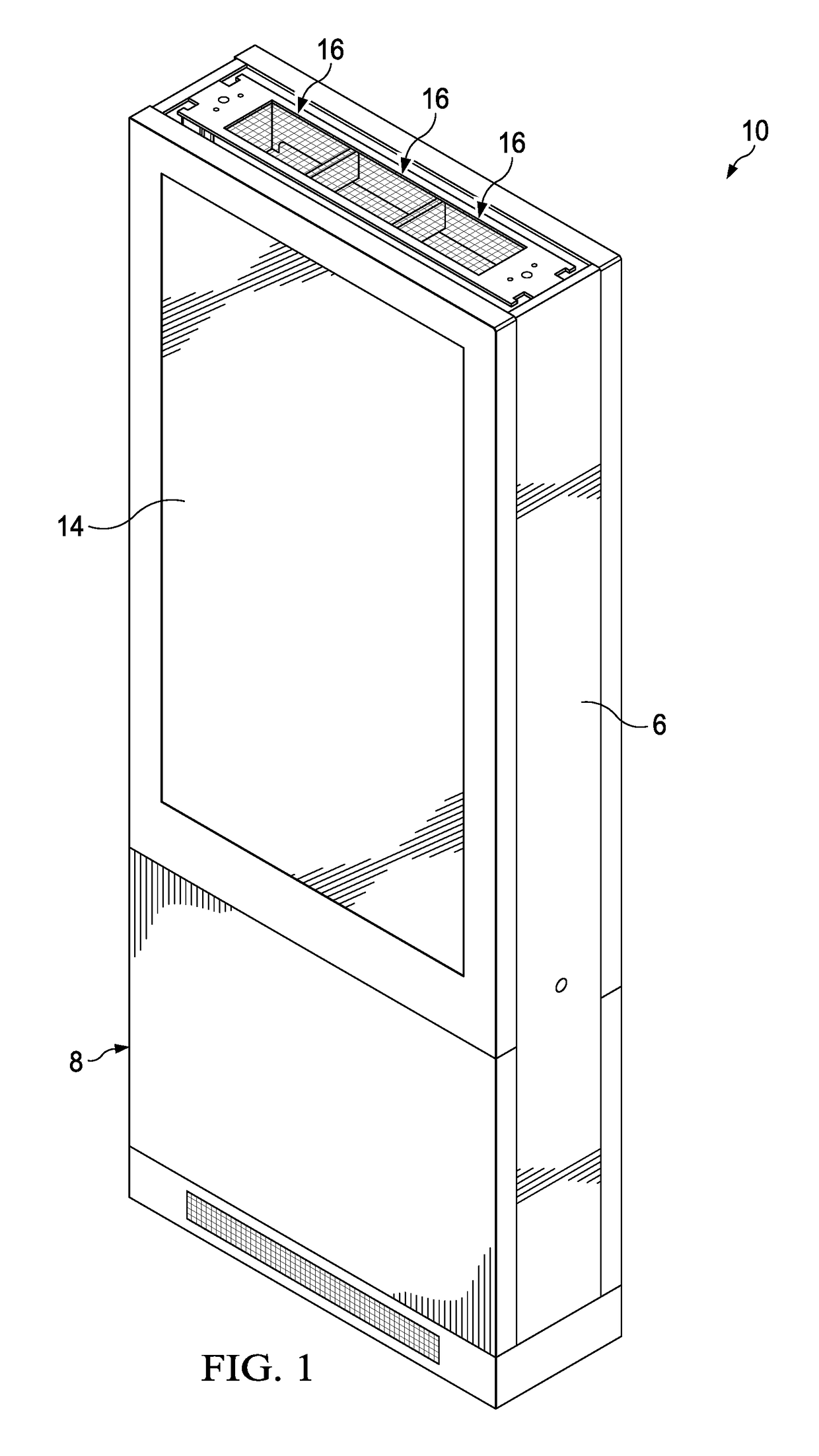
[0032]FIG. 1 is a front perspective view of an exemplary assembly 10 in accordance with the present invention. The assembly 10 may comprise one or more display assemblies 14 placed within a housing 6. The housing 6 may comprise a stand 8 for mounting the assembly 10 to the ground. However, in other exemplary embodiments, the assembly 10 may be ...


PUM


Abstract

A field serviceable apparatus includes a first and second display assembly hingedly mounted to a frame in a back to back arrangement. At least one of the display assemblies has a transparent layer, an electronic display, a first channel that receives circulating gas, and a second channel that receives ambient air. A cavity is located in the space between the rear surfaces of the display assemblies and the frame and contains a fixed plate for receiving electronic components. The cavity and the first channel are part of a closed loop pathway, while the second channel is part of an open loop pathway.

Description

CROSS-REFERENCE TO RELATED APPLICATION[0001]This application claims the benefit of U.S. Provisional Patent Application Ser. No. 62 / 491,106 filed Apr. 27, 2017 and U.S. Provisional Patent Application Ser. No. 62 / 502,337 filed May 5, 2017. The disclosures of which are hereby incorporated by reference in their entirety.TECHNICAL FIELD[0002]Exemplary embodiments of the present invention relate generally to assemblies for electronic displays.BACKGROUND AND SUMMARY OF THE INVENTION[0003]Electronic displays have grown in popularity not only for indoor use, but also for outdoor use. One exemplary application, without limitation, is the digital out of home advertising market where the electronic displays are increasingly replacing the use of static posters. The use of electronic displays is advantageous because they allow images to be changed quickly as well as permit the use of videos and interactive displays, among other benefits. Such displays have been placed in many locations, including...

Claims


Application Information

Patent Timeline
Patent Type & Authority Applications(United States)
IPC IPC(8): G09F13/04H05K7/20H05K5/02H05K5/00H05K7/14G09F21/04G09F9/30
CPCG09F13/0413H05K7/20972H05K5/0226H05K5/0017H05K5/0247H05K7/1488G09F21/04G09F9/30G09F2013/044G09F2013/0445G09F9/35G02F1/133308G02F1/133385G02F2201/36G02F1/133342G02F1/133331G09F21/042H05K5/03H05K7/20145H05K7/20736H05K7/20954H05K5/0018G02F1/133382G09F13/044G09F13/0445G02F1/13338
Inventor DUNN, WILLIAMO'CONNOR, KEVINDIAZ, MARCOS
Owner MFG RESOURCES INT INC
Learn More