Delivery unit

a technology of delivery unit and delivery head, which is applied in the direction of machines/engines, transportation and packaging, liquid fuel engines, etc., can solve the problems of hydraulic loss, unfavorable energy terms, and high cost of rotational speed control

Inactive Publication Date: 2011-08-04
ROBERT BOSCH GMBH
View PDF9 Cites 0 Cited by
  • Summary
  • Abstract
  • Description
  • Claims
  • Application Information

AI Technical Summary

Benefits of technology

[0005]According to a second embodiment, at least one control opening connected to the outlet side is arranged in a region of the first separating web which lies behind the first transition point in the direction of rotation, as in this way the inner sealing of the delivery unit can be controlled.

Problems solved by technology

A rotational speed control is energy-efficient but very expensive as an electric motor must be used, the rotational speed of which can be controlled.
In the case of bypass control, the fluid is delivered from the outlet via a bypass back to the inlet, which however is unfavorable in energy terms and is associated with hydraulic losses.

Method used


Image

  • Delivery unit
  • Delivery unit
  • Delivery unit

Examples


Embodiment Construction

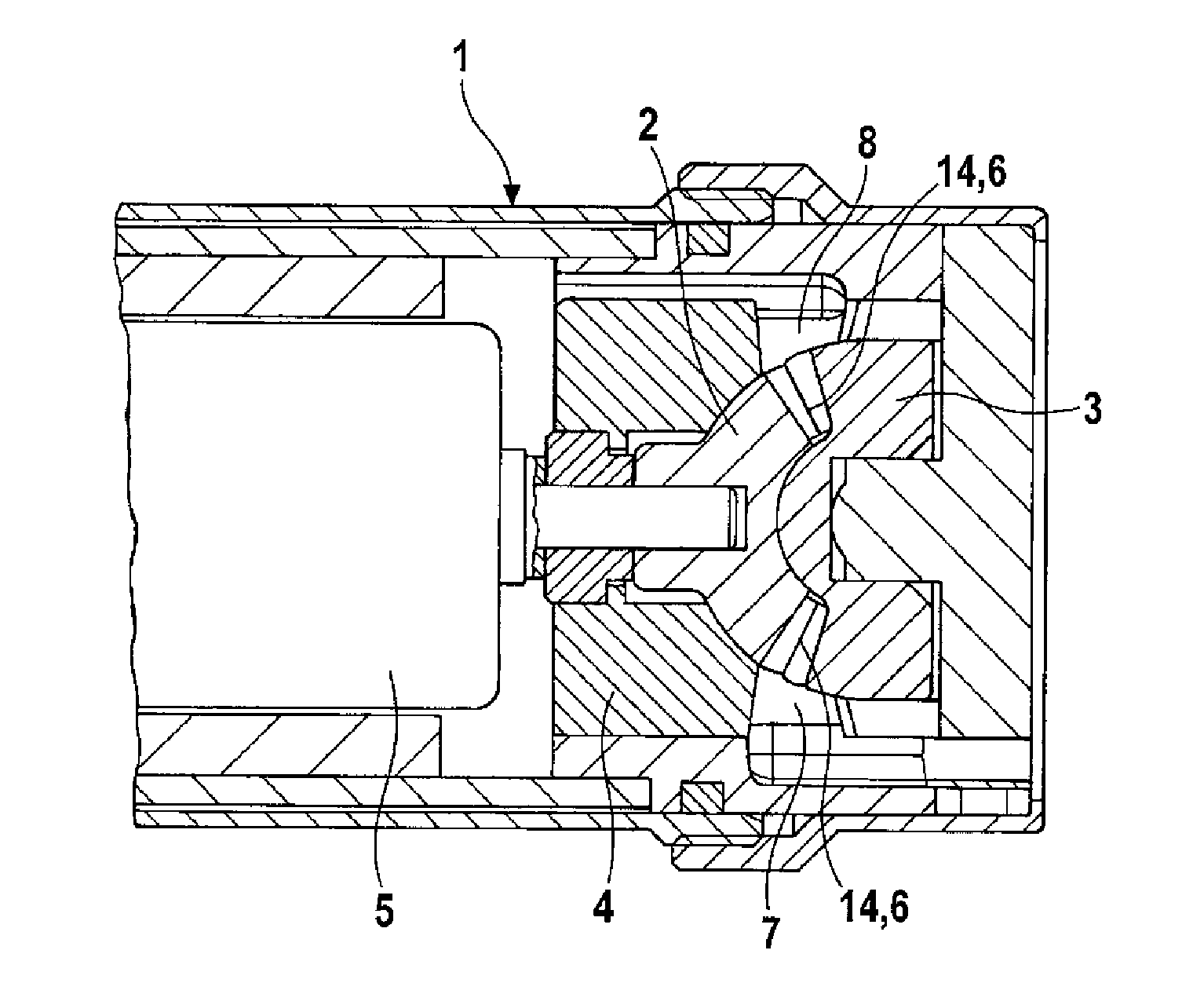
[0011]FIG. 1 shows in section a delivery unit to which the invention could be applied.

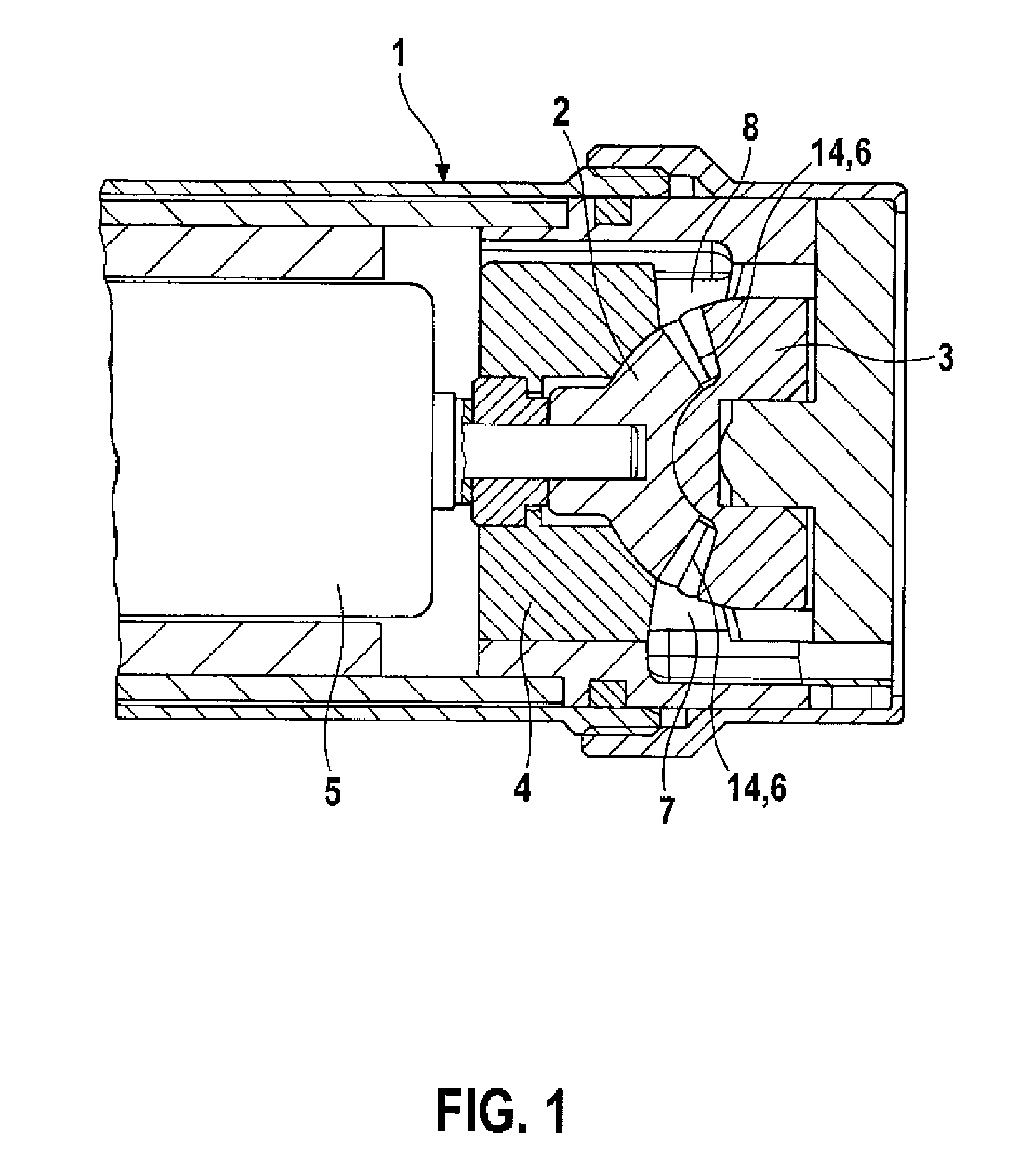
[0012]The delivery unit 1 has a drive rotor 2 and an output rotor 3 driven by the drive rotor 2 which are both mounted in a rotor housing 4. The drive rotor 2 is driven by a motor 5, for example an electric motor, via a driveshaft. The two rotors 2, 3 each have a spur toothing6, for example a cycloidal spur toothing, which interact with each other in a meshing manner and draw fluid in through at least one inlet 7 in the rotor housing 4 and push said liquid out through an outlet 8 in the rotor housing 4 following the positive displacement principle. Working chambers 14 are formed between the spur toothings 6 of the rotors 2, 3. The axes of rotation of the two rotors 2, 3 extend obliquely to each other and thus enclose an angle other than 180 degrees so that the volume of the working chambers 14 alternately increases and decreases during a revolution of the drive rotor 2. At the inlet 7 the volume of...


PUM


Abstract

Delivery units are already known which have a drive rotor and an output rotor driven by the drive rotor, which are supported in a housing, interact in a meshing manner through a spur toothing in each case and draw fluid through at least one inlet and push said fluid out through an outlet, wherein the inlet and the outlet are separated from each other by two separating webs. In order to control the flow rate through the delivery unit, a rotational speed control, a bypass control, or, for gases, a suction throttling, for example, can be carried out. A rotational speed control is energy efficient, but very expensive, because an electric motor must be used, the rotational speed of which can be controlled. In the bypass control, the fluid is delivered from the outlet through a bypass back to the inlet, which however is energetically unfavorable and connected to hydraulic losses. The delivery unit according to the invention is improved in such a way that on the inlet side the flow rate can be controlled very easily and with few hydraulic losses and on the outlet side the inner compression can be adjusted in the event of delivery of gases. According to the invention, at least one of the separating webs (9,10) has at least one control opening (12), the opening cross-section of which can be controlled with a control slide (13).

Description

BACKGROUND OF THE INVENTION[0001]The invention relates to a delivery unit. A delivery unit is known already from DE 10 2004 026 048 A1 comprising a drive rotor and an output rotor driven by the drive rotor which are mounted in a housing, interact in a meshing manner via a respective spur toothing and draw fluid through at least one inlet and push said fluid out through an outlet, wherein the inlet and the outlet are separated from each other by two separating webs. In order to control the flow rate through the delivery unit, a rotational speed control, a bypass control or, for gases, a suction throttling can, for example, be carried out. A rotational speed control is energy-efficient but very expensive as an electric motor must be used, the rotational speed of which can be controlled. In the case of bypass control, the fluid is delivered from the outlet via a bypass back to the inlet, which however is unfavorable in energy terms and is associated with hydraulic losses.SUMMARY OF THE...

Claims


Application Information

Patent Timeline
Patent Type & Authority Applications(United States)
IPC IPC(8): F01D17/00
CPCF04C3/085F04C2240/30F04C14/10Y10T137/85978
Inventor STEIDTEN, THOMASSAMERSKI, INGONOWITZKY, INGOHAEGELE, NICCOLOSCHRADER, JENSDAIMER, GUIDO
Owner ROBERT BOSCH GMBH
Why Eureka
Try Eureka