Air cleaner housing

a cleaner and housing technology, applied in the direction of separation processes, dispersed particle separation, chemistry apparatus and processes, etc., can solve the problems of defective sealing, failure of sealing function, and failure of the engagement mechanism to keep the gaps sealed between the filter element and the two cases, so as to facilitate the clamping of the cases and improve the free-flow of design

Active Publication Date: 2016-08-25
TOYOTA BOSHOKU KK
View PDF6 Cites 0 Cited by
  • Summary
  • Abstract
  • Description
  • Claims
  • Application Information

AI Technical Summary

Benefits of technology

[0007]Accordingly, it is an object of the present invention to provide an air cleaner housing that facilitates the closing of the two cases, while limiting defective sealing by restricting coupling of the two cases when the two cases are displaced from the predetermined positions.
[0009]In the above structure, if the second case is displaced from the predetermined position relative to the first case when closing the opening of the first case, the first and second closing stoppers interfere with each other and stop the second case from closing the opening of the first case. This prevents one of the cases from being displaced relative to the filter element and ensures that gaps are sealed between the filter element and the two cases. Since the first closing stopper and the second closing stopper are included in the clamp mechanism, the first and second closing stoppers share space with the clamp mechanism. This reduces the space occupied by the first and second closing stoppers.
[0010]Thus, there are fewer limitations to the layout of components around the air cleaner housing in the engine compartment, and the freedom of design may be improved for the engine compartment. Further, since the clamp mechanism includes the first and second closing stoppers, the person that clamps the two cases with the clamp can check whether or not the opening of the first case is closed by the second case when checking the clamping of the clamp mechanism. This facilitates the clamping of the cases.

Problems solved by technology

However, in the air cleaner housing disclosed in Japanese Laid-Open Patent Publication No. 9-14065, the engagement mechanism may not be able to keep the gaps sealed between the filter element and the two cases.
In such a case, the seal may fail to function properly.
This leads to defective sealing and adversely affects the filtering performance.
This increases the workload.

Method used


Image

  • Air cleaner housing
  • Air cleaner housing
  • Air cleaner housing

Examples


Embodiment Construction

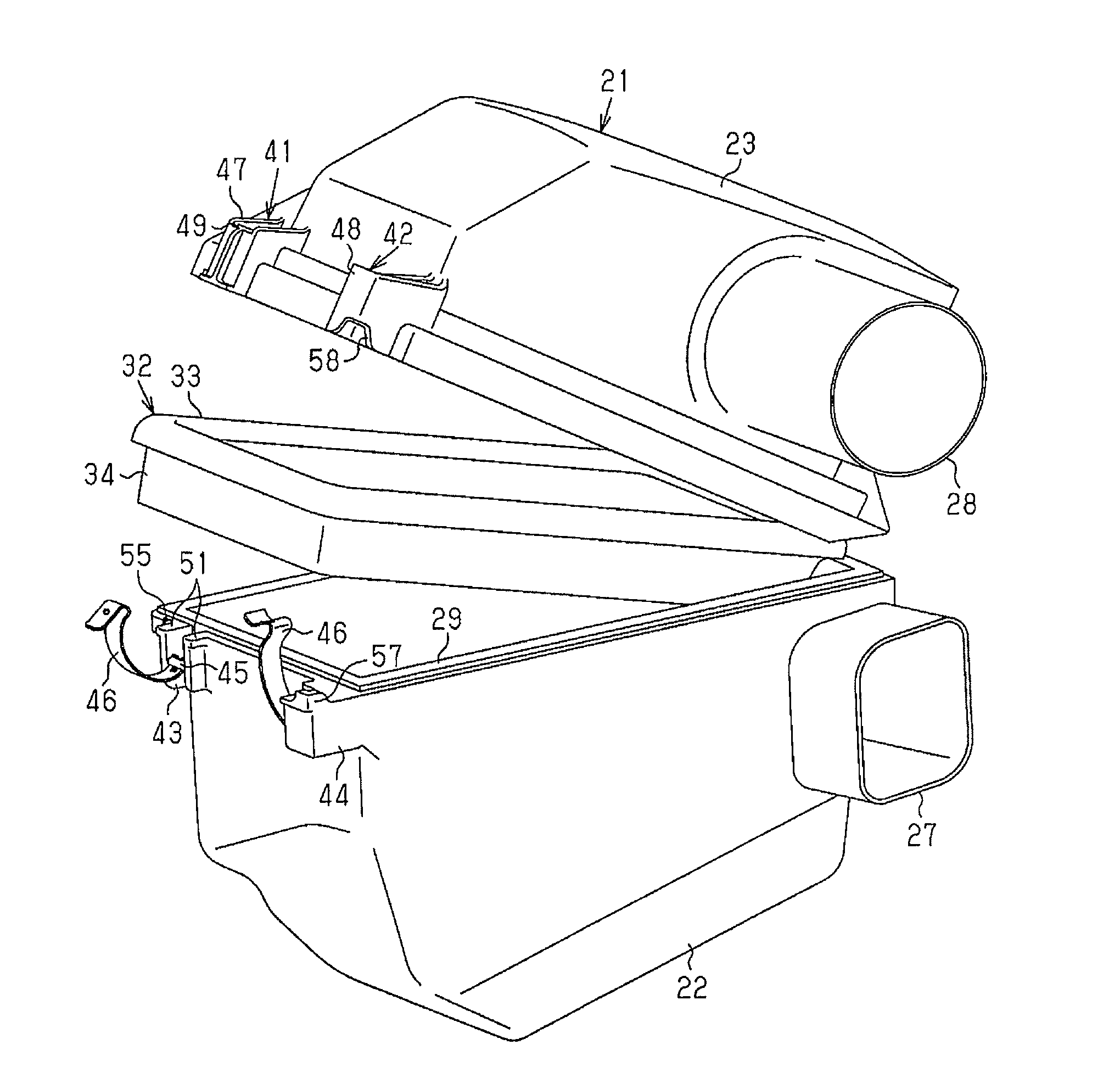
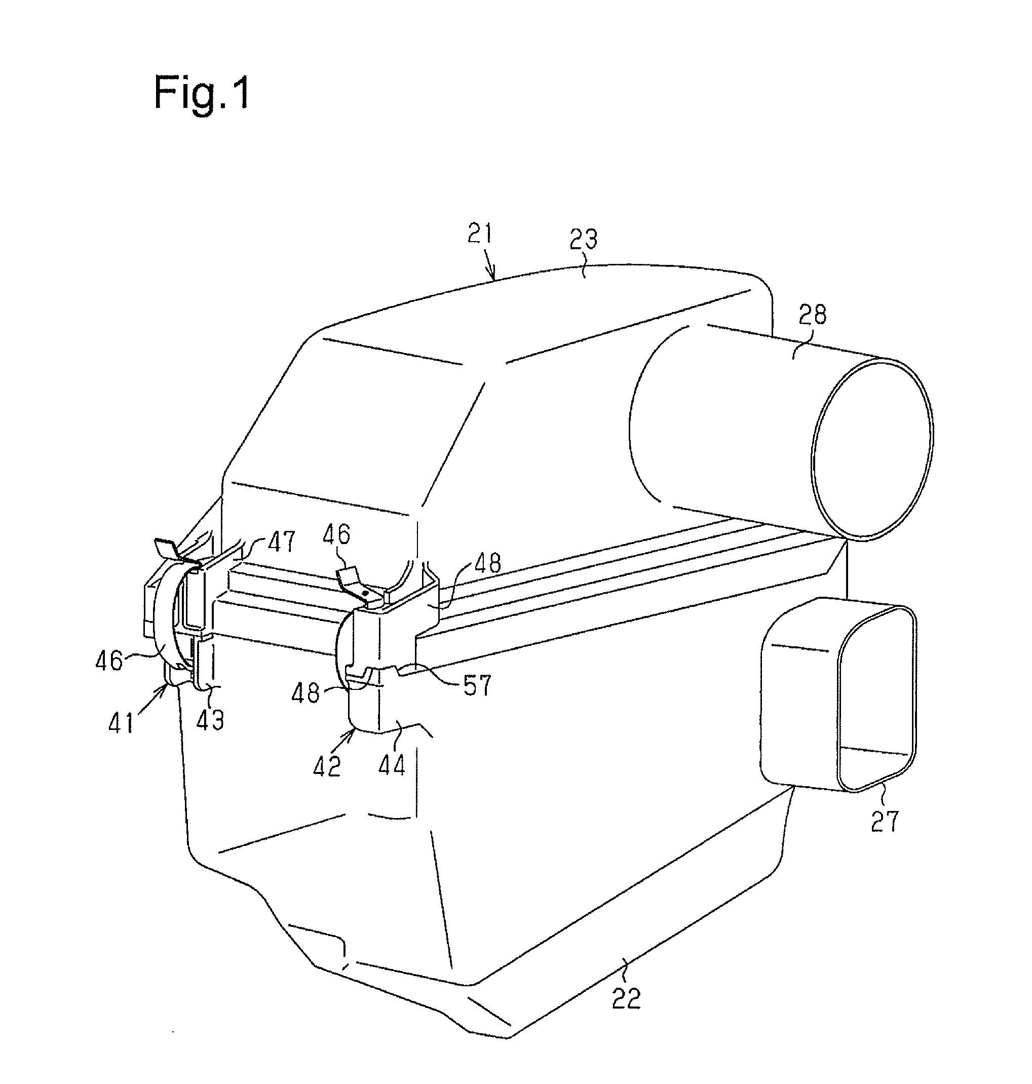
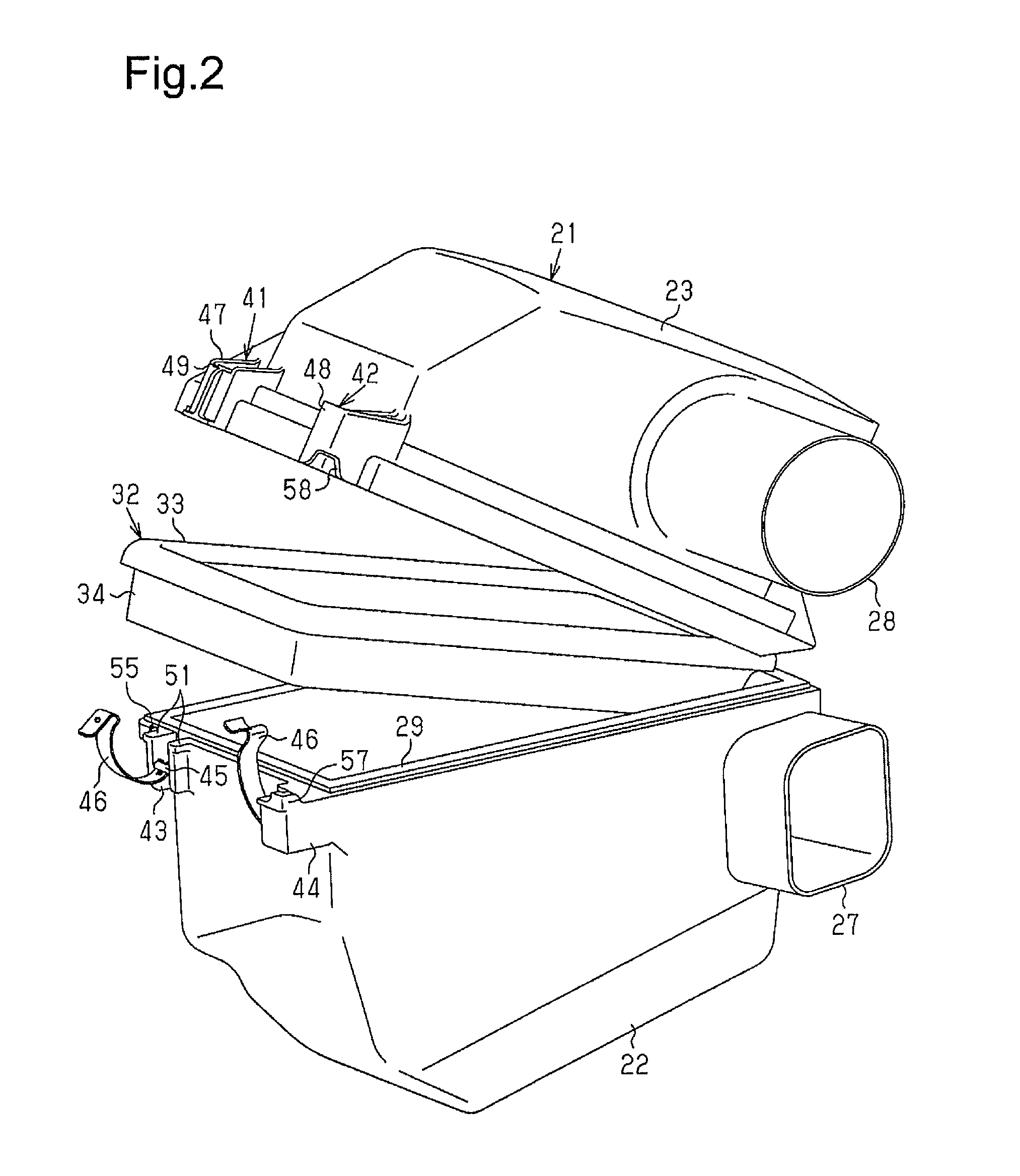
[0027]An air cleaner housing according to one embodiment of the present invention will now be described with reference to the drawings.

[0028]As shown in FIGS. 1 and 2, an air cleaner housing (hereinafter, referred to as the housing 21) is tetragonal in a plan view and includes a lower case 22 (first case) and an upper case 23 (second case). The lower case 22 is located in an engine compartment of a vehicle. The upper case 23 is coupled to the lower case 22 so that the upper case 23 can open and close an upper opening of the lower case 22.

[0029]As shown in FIG. 3, two U-shaped catches 24 are formed integrally with a rear portion of the lower case 22, and two projections 25 are formed on a rear portion of the upper case 23. The two catches 24 and the two projections 25 form two hinges 26. The upper case 23 is moved on the lower case 22 toward the rear to insert the projections 25 of the upper case 23 into the catches 24 of the lower case 22. To open the upper opening of the lower case...


PUM

PropertyMeasurementUnit
angleaaaaaaaaaa
angleaaaaaaaaaa
angleaaaaaaaaaa

Abstract

An air cleaner housing is provided with a first case including an opening, a second case capable of opening and closing the opening of the first case, a clamp mechanism including a clamp that holds the second case in a state closing the opening of the first case, a filter element arranged between the first case and the second case, and a first closing stopper and a second closing stopper configured to interfere with each other when the second case is displaced from a predetermined position relative to the first case thereby stopping the second case from closing the opening of the first case. The first closing stopper and the second closing stopper are included in the clamp mechanism.

Description

BACKGROUND ART[0001]The present invention relates to an air cleaner housing that accommodates a filter element, which filters air that is delivered to an engine.[0002]A typical air cleaner housing includes two cases. One of the two cases closes and opens an opening of the other case. A filter element is held between the two cases.[0003]Japanese Laid-Open Patent Publication No. 9-14065 discloses such an air cleaner housing.[0004]The air cleaner housing disclosed in the publication includes a lower case and an upper case, which opens and closes an upper opening of the lower case. A filter element is arranged between the two cases. The upper case is moved along the lower case to couple the upper case to the lower case when assembling the air cleaner housing. The air cleaner housing includes an engagement mechanism to restrict movement of the upper case, after the two cases are coupled to each other, in a direction opposite to the direction the upper case is coupled to the lower case. T...

Claims


Application Information

Patent Timeline
Patent Type & Authority Applications(United States)
IPC IPC(8): B01D46/00
CPCB01D46/0005B01D46/0004B01D46/10
Inventor ENDO, DAISUKEKATO, SHINYA
Owner TOYOTA BOSHOKU KK
Why Eureka
Try Eureka