
Sealing system pump piston

a sealing system and plunger piston technology, applied in the direction of positive displacement liquid engine, borehole/well accessories, liquid fuel engine, etc., can solve the problems of loss of sealing ability, and packing beginning to wear into the packing bore, so as to avoid wash

Active Publication Date: 2020-03-17
ST9 GAS & OIL LLC
View PDF3 Cites 1 Cited by
  • Summary
  • Abstract
  • Description
  • Claims
  • Application Information

AI Technical Summary

Benefits of technology

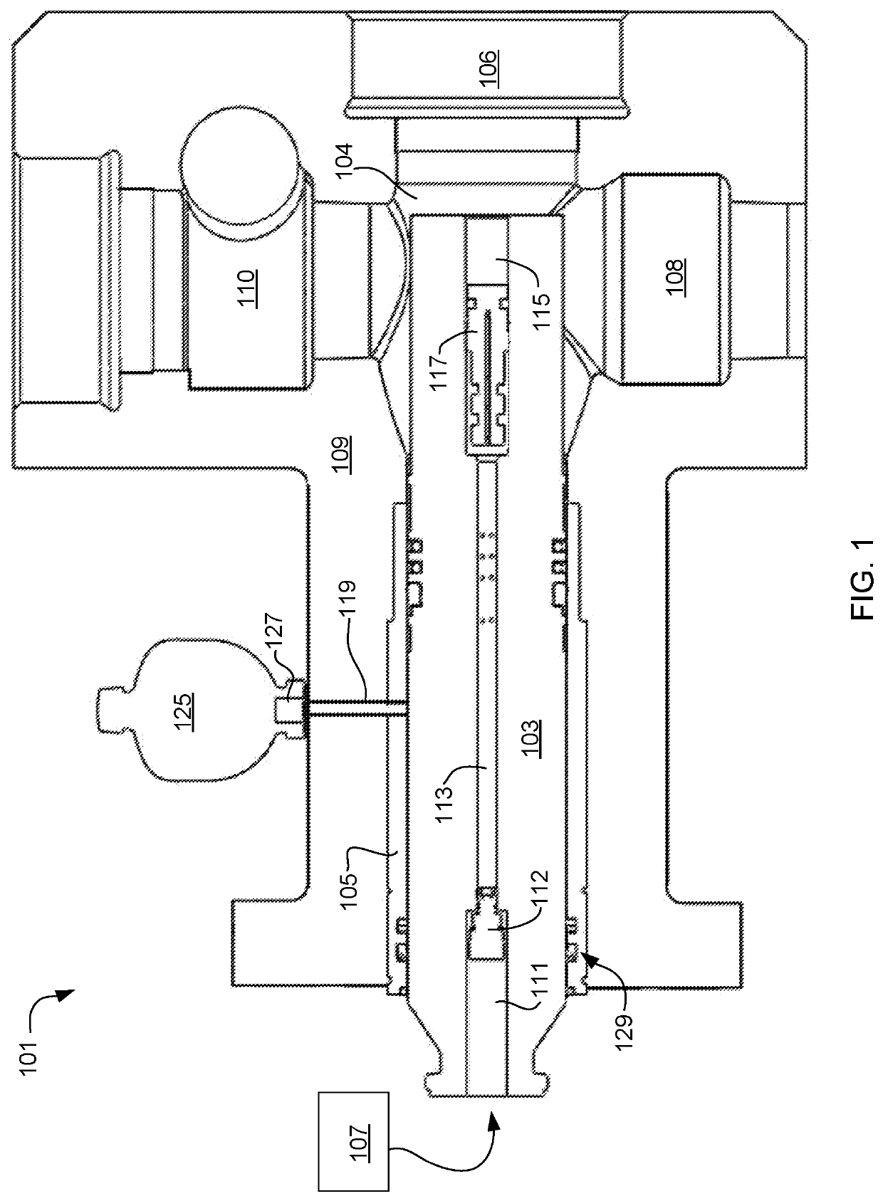
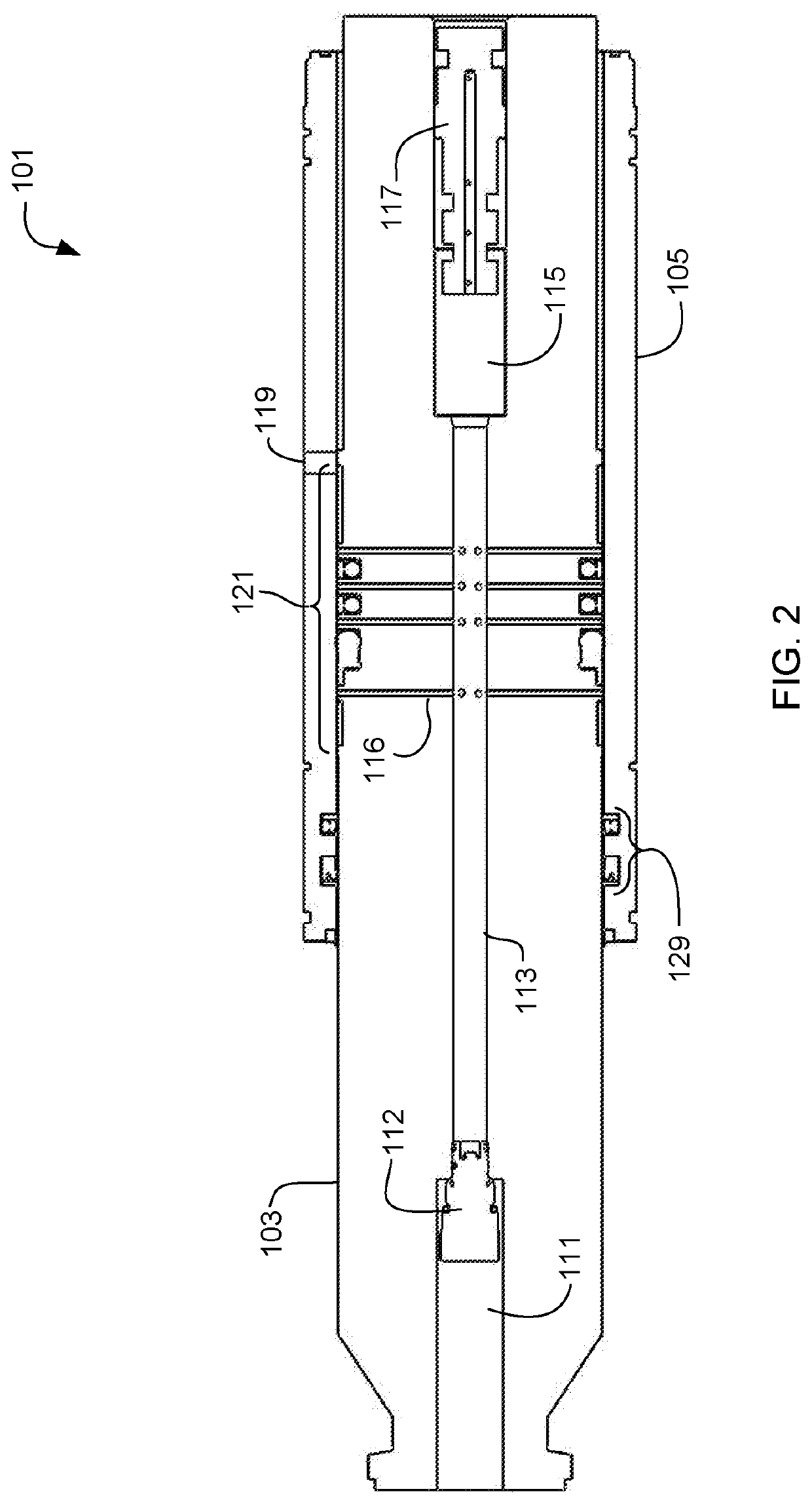
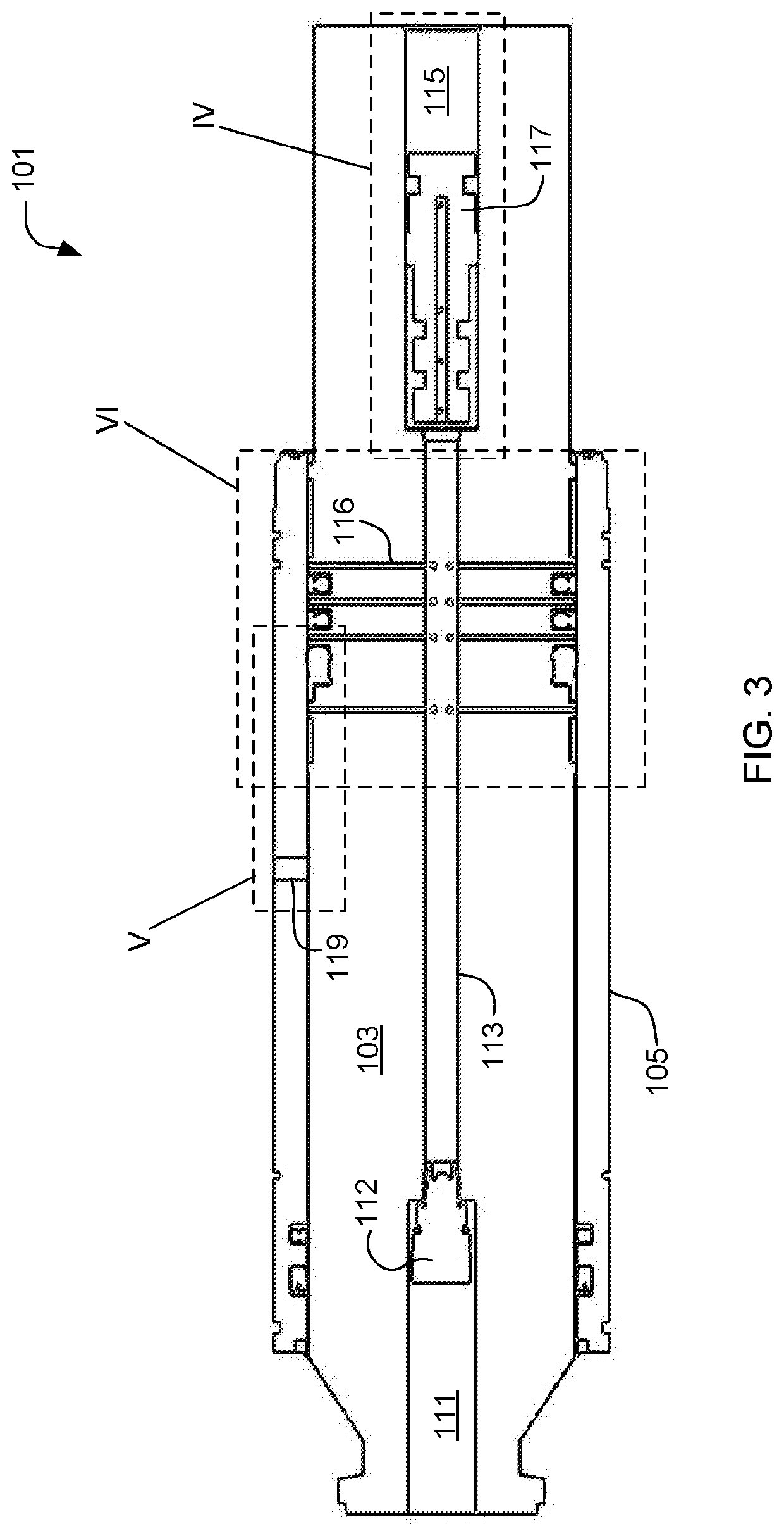
[0008]It is an object of the present application to provide a lubricating sealing system within a plunger piston of a reciprocating pump. The plunger reciprocates within a fluid end and is used to pump fluid / proppant from a suction valve to a discharge valve with each reciprocating motion. The lubricating sealing system is configured to apply a quantity of pressurized lubrication outward from the plunger directly to a gap between the plunger and a sleeve. As the plunger reciprocates against the sleeve in the fluid end, the pressurized lubrication is passed over the seals and acts as a barrier to the introduction of proppant and contaminants into the seal vicinity, thereby avoiding wash out.
[0009]It is a further object of the present application that the lubrication be introduced into a central passage within the plunger through a non-return valve in the plunger. Pressure is created within the lubrication passages of the plunger from the movement of the plunger itself. An intensification valve is located at a base of the plunger and translates within a channel as the plunger reciprocates. Movement of the intensification valve induces movement of the lubrication from the central passage outward through a plurality of outlet tubes where it fills the gap between the plunger and the sleeve.
[0010]A further object of the present application is to use an accumulator in fluid communication with the gap and the lubrication fluid. The accumulator includes a bladder to regulate pressure in the system so as to prevent pressures from exceeding the limits of the upper seals. The accumulator includes a solenoid valve to restrict outward flow from the accumulator to the gap.
[0011]Ultimately the invention may take many embodiments but features the ability to insert lubrication fluid directly between the sleeve and the plunger piston in a pressurized manner in order to effectively act as a barrier to proppant introduction at the seals. In this way, this assembly overcomes the disadvantages inherent in the prior art.

Problems solved by technology

Properly maintaining fluid ends in high-cycle environments is not easy, since packing bores can wash out at any time.
If a packing or grease system fails, the packing bore gets cut by the high-pressure water, causing it to lose its ability to seal.
The use of stainless steel fluid ends achieves higher cycle hours, but with those longer hours of operation, the packing begins to wear into the packing bore, creating waves.
Eventually, the packing bore becomes so severely washboarded that the packing will not seal.
Washouts and washboarding can be weld repaired, but that drastically reduces the strength of the fluid end because welded material cannot compare to the strength of forged stainless steel.
Three fundamental flaws with conventional stuffing box packing remain: 1) Manual adjustment by a nut or other means to give the correct amount of sealing force is subjective whether at first fit or once worn; 2) The lubrication of the packing and the fastidious maintenance of the boundary layer fluid film between the seal and reciprocated parts are critical if meaningful life is to be achieved; and 3) The introduction and contact of the proppant with the sealing components often creates complications.

Method used


Image

  • Sealing system pump piston
  • Sealing system pump piston
  • Sealing system pump piston

Examples


Embodiment Construction

[0023]Illustrative embodiments of the preferred embodiment are described below. In the interest of clarity, not all features of an actual implementation are described in this specification. It will of course be appreciated that in the development of any such actual embodiment, numerous implementation-specific decisions must be made to achieve the developer's specific goals, such as compliance with system-related and business-related constraints, which will vary from one implementation to another. Moreover, it will be appreciated that such a development effort might be complex and time-consuming but would nevertheless be a routine undertaking for those of ordinary skill in the art having the benefit of this disclosure.

[0024]In the specification, reference may be made to the spatial relationships between various components and to the spatial orientation of various aspects of components as the devices are depicted in the attached drawings. However, as will be recognized by those skille...


PUM


Abstract

A lubricating sealing system for a fluid end includes a fluid end, a sleeve, a plunger, and a lubrication system. The sleeve is coupled to an internal surface of the fluid end. The plunger reciprocates in a linear manner through the sleeve and into a pressure chamber of the fluid end. The lubrication system is in communication with the plunger and configured to provide lubricant through an interior of the plunger for routing to surfaces between the plunger and the sleeve. The lubricant is pressurized and moved via the reciprocating of the plunger and create a positive pressure on the lubricant over the pressures experienced in the pressure chamber of the fluid end. The positive pressure creates a barrier and pushes away contaminants from the plunger seals thereby avoiding wash out.

Description

CLAIM OF PRIORITY[0001]This application claims the benefit of U.S. Provisional Application No. 62 / 545,854, filed 15 Aug. 2017. The information contained therein is hereby incorporated by reference.BACKGROUND1. Field of the Invention[0002]The present application relates generally to a reciprocating pump, and in particular to a lubricating sealing system for a plunger piston in the reciprocating pump.2. Description of Related Art[0003]Properly maintaining fluid ends in high-cycle environments is not easy, since packing bores can wash out at any time. If a packing or grease system fails, the packing bore gets cut by the high-pressure water, causing it to lose its ability to seal. The use of stainless steel fluid ends achieves higher cycle hours, but with those longer hours of operation, the packing begins to wear into the packing bore, creating waves. This is called washboarding.[0004]Eventually, the packing bore becomes so severely washboarded that the packing will not seal. Washouts ...

Claims


Application Information

Patent Timeline
Patent Type & Authority Patents(United States)
IPC IPC(8): F04B53/14F04B53/18F04B19/22F04B53/16E21B43/267
CPCF04B53/164F04B19/22F04B53/18F04B53/143E21B43/267
Inventor BUCKLEY, CHRIS
Owner ST9 GAS & OIL LLC
Learn More